9 Installation of Mechanical Override Models
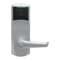
2. Preparing the outside housing for the installation of
the lever handle
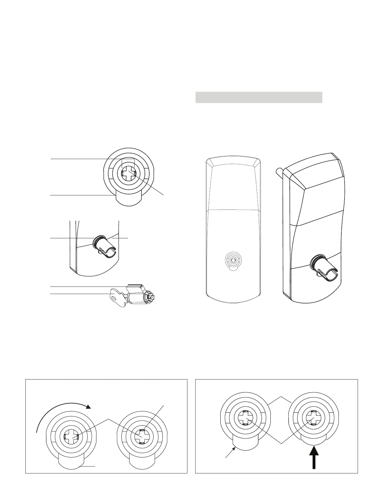
1. Insert the cylinder (J) to be used as a tool or equivalent tool
to rotate the override shaft (L) and turn it clockwise until
it stops so that the two small indents (M) on the cross are
now vertically in line. (Fig.1)
2. Push in the lever catch (F) firmly. (see Fig. 2) to be flush
with drive tube diameter
(F)
(L)
(E)
(M)
(C)
(N)
(J)
Fig. 2
Lever catch (F)
Push lever
catch (F) in
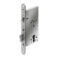
1. Upon unpacking, the lock housing with mechanical
override should look like the diagram below with:
(M) The small indents on the cross of the override shaft in
line Horizontally
(C) The nylon washer and the spring washer (not for lever
feel) on the drive tube
(F) The lever catch in the out position
(J) Cylinder and 2 keys for 660 K/C included in the hardware
bag
IMPORTANT
Assemble the lever, cylinder and lock components before
affixing the entire unit to the door.
Fig. 1
(F)
Override
Shaft (L)
Indents (M)
In vertical
position
(L)
(E)
7 Installation of Mechanical Override Models
35
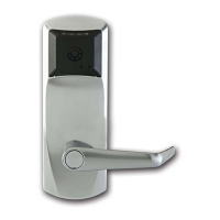
E7900 Series
KD10114-E-1122