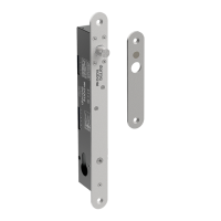
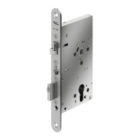
5. Release the latch bolt (L). Position the latch bolt so that
the bottom tooth of the anti-friction latch (F) remains in-
side the mortise case as shown.
IMPORTANT
If the tooth of (F) is outside the mortise, you will not be able
to re-assemble the faceplate on the mortise.
L
F
L
F (tooth)
mortise
bottom view
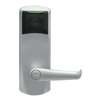
6. If the auxiliary latch (X) is shaped like a triangle, there is
no need to change its handing.
X (triangular = OK)
If the auxiliary latch (X) is a crescent shape, remove it, turn
it 180°, and replace it. The auxiliary latch slides easily in and
out of the mortise.
X (crescent = must be reversed)
180°
(re-insert)
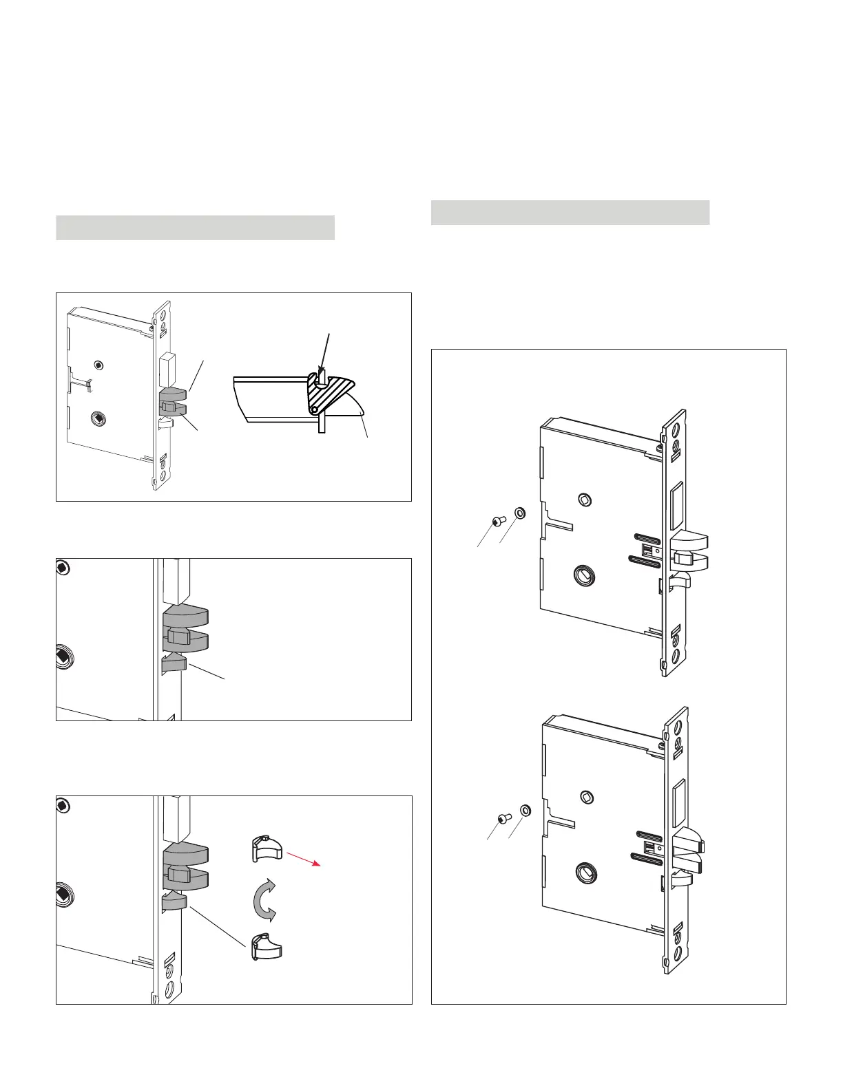
7. Assemble back screw (V) and lock washer (W) if appli-
cable. The screw (V) must be tightened.
IMPORTANT
Screw (V) must not touch the back wall of mortise cut-out
on the door
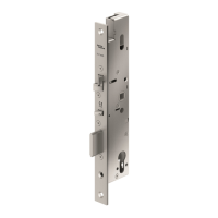
8. The mortise should look like the diagram below. (Check
the orientation of the latch bolt and auxiliary latch.)
Check the bevel of the mortise and change it if required
as described in section 3.3, page 10.
For LH (left hand) and
RHR (right hand reverse)
For RH (right hand) and
LHR (left hand reverse)
W
V
W
V
ASM
APPENDIX A Mortise Models
44 E7900 Series
KD10114-E-1122