MAINTENANCE SECTION 5
Page 21
DRESSTA OM560C99/1E
BRAKES
VENTING THE SYSTEM
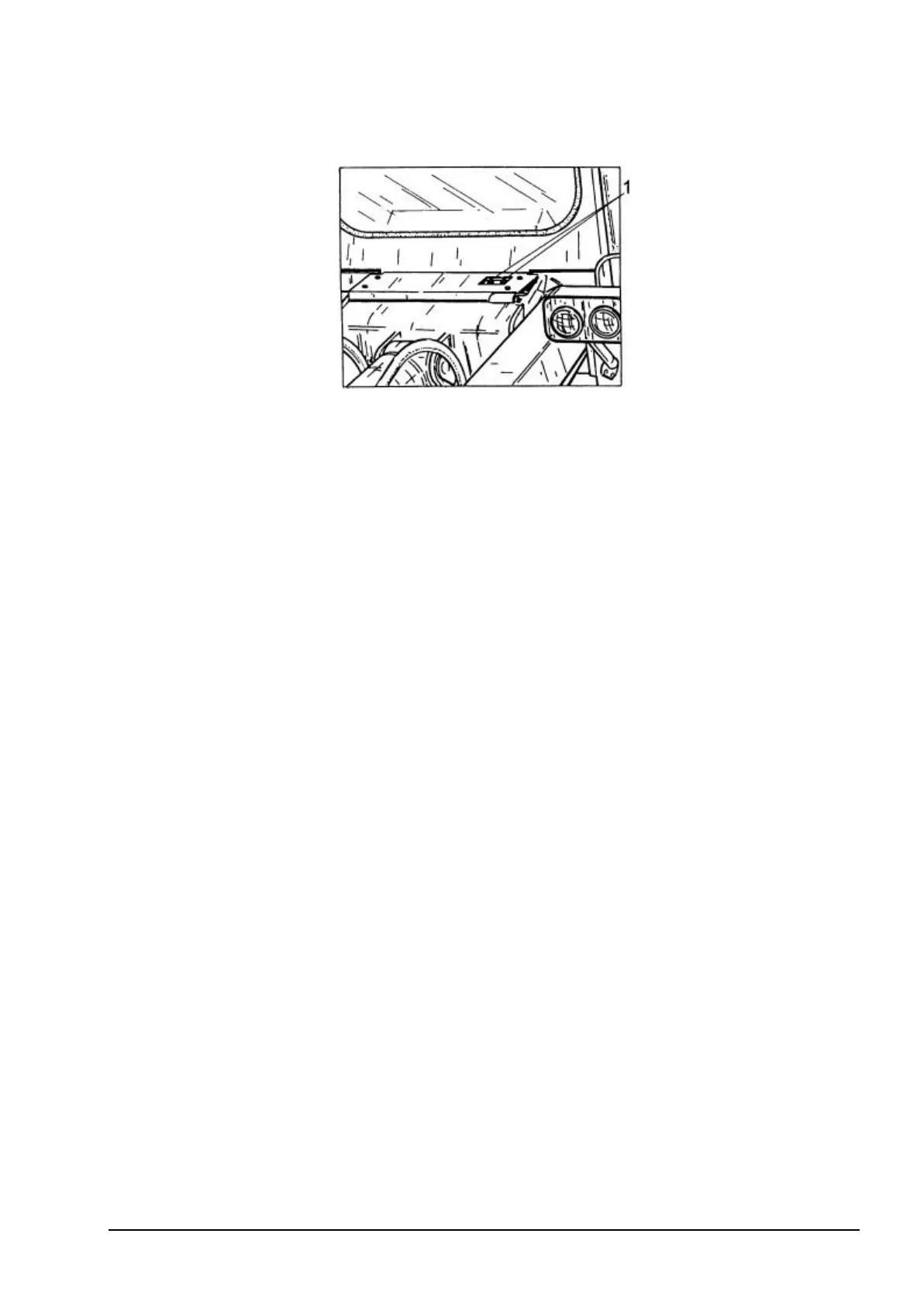
Fig. 5.13. Differential Valve.
1 - Vents
Two servicemen are required to perform the service. Vented are brakes of individual wheels,
differential valve signaling a failure of one brake system and the transmission disconnecting valve.
The differential valve is located on the front wall of the cab below the windscreen (access thru a
cutout in the platform), Fig. 5.13. The brakes and differential valve should be vented in accordance
with the procedure specified below (total of 6 vents).
1. After removing the protecting rubber cap install a transparent plastic tube on the vent valve. Put
the other end of the tube in a small amount of oil in a clean container.
2. Open the vent valve slightly by turning it, simultaneously the operator in the cab should depress
lightly the brake pedal (brake valve). Let the oil with air flow until the outflowing oil is free from air
bubbles.
3. Turn off the vent valve and release the brake pedal.
4. Install the protecting rubber cap.
5. Check that the valves are securely tightened with the brake valve fully open.
Pour the drained, clean oil into the transmission.
The venting procedure of the transmission disconnecting circuit is as follows:
1. Start the engine and let it operate at low idle with the transmission neutral lock lever and parking
brake applied.
2. Place the transmission disconnect switch in brake position with the transmission disconnected,
see INSTRUMENTS AND CONTROLS
3. Loosen hose fitting 2 of hose 1, Fig. 5.14. on the transmission at the transmission
disconnecting valve by app. 1 turn.
4. Depress slightly the brake pedal. Observe the outflow of air and oil at loosened hose
connection.
5. Tighten the connection when clear oil without air bubbles starts to flow.