OPERATING SECTION 4
Page 23
DRESSTA OM560C99/1E
CAB HEATING AND VENTILATION
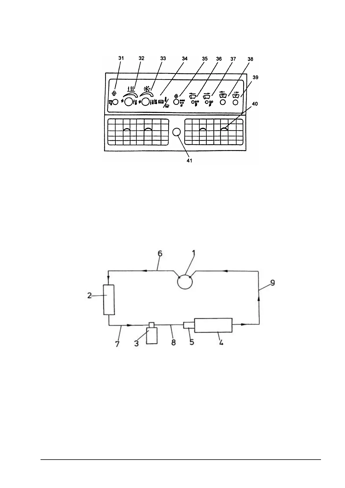
Fig. 4.13. Side Control Panel
31. Heater Fan Control Switch
32. Heater Temperature Control Knob
33. Air Conditioner Temperature Control Knob
34. Main Switch
35. Window Defroster Fan Switch (If Equipped)
36. Windshield Wiper Switch
37. Rear Window Wiper Switch
38. Windshield Washer Switch
39. Rear Window Washer Switch
40. Air Control Knob
41. Air Intake Mode Control Knob
For description of controls refer to Section 4.3
4.6.3. AIR CONDITIONER
Fig. 4.14. Block Diagram of A/C Connections
The wheel loader may be equipped with an air conditioner to reduce air temperature and relative
humidity inside the cab. An air conditioner consists of the following principal components:
1. Compressor – V-belt driven thru pulley mounted on the LH side of the engine
2. Condenser - radiator mounted
3. Dehumidifier – mounted on a bracket on the RH side of rear frame
4. Evaporator – RH side cab wall mounted
5. Relief valve – integrated with evaporator
The a/m components are connected with hoses 6+9, A/C system is filled with R-134A gas.
IMPORTANT: If A/C system refilling is required contact Construction Equipment Authorized
Distributor. The system must be filled in accordance with the manufacturer’s instructions.