OPERATING SECTION 4
Page 19
DRESSTA OM560C99/1E
INSTRUMENTS AND CONTROLS
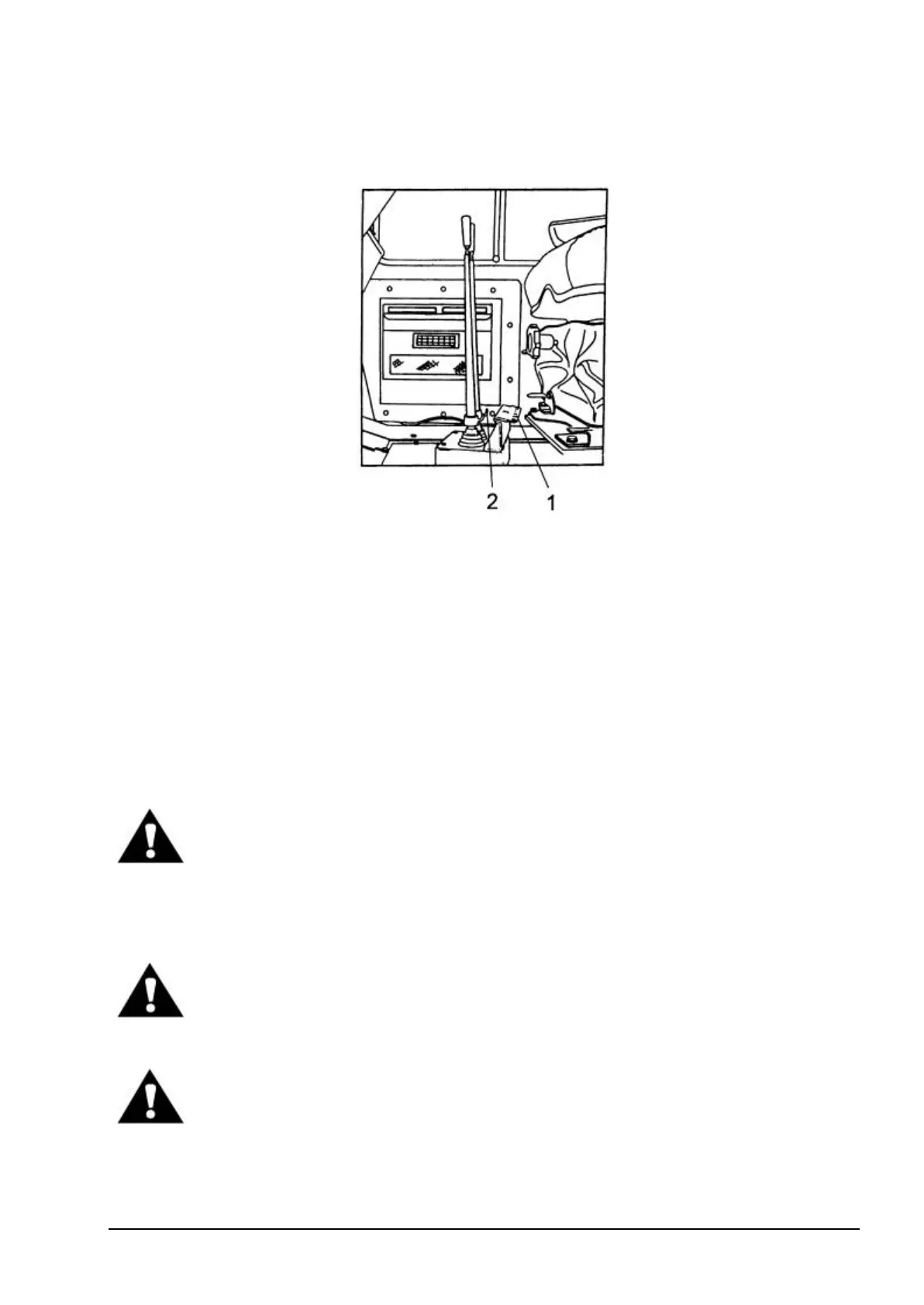
53. CONTROL LEVER LOCKING PLATE (FIG. 4.8)
Fig. 4.8. Control Lever Locking Plate
1- Locking Plate 2 - Locking Bar
Locking plate 1 is used to lock the control levers in the neutral position. In the drawing the plate is
shown in the non-locked position.
54. HAZARD LIGHTS WITH CONTROL LIGHT
Switch on hazard lights in case of malfunction of loader in a hazardous place e.g. building site.
Red light comes on when hazard lights are switched on.
55. DIRECTIONAL SIGNAL SWITCH
Used to switch on right or left turn signal (forward or backward movement of the switch).
Green lights come on when the directional signal is switched on.
WARNING! When roading the machine, engage the hydraulic control lever
locking plate. Accidental actuation of the levers may cause personal injury or
damage of the machine.
4.4. SUSPENSION SEAT
WARNING! Before driving the machine, adjust the seat and fasten the seat belt.
Adjust the seat belt to fit snugly and low around the hips to lessen the chance
and severity of injury in the event of an accident. Never wear the seat belt
across the abdomen.
WARNING! Do not adjust the seat position while the machine is moving, because
a lose of control may result.
Stop the machine, apply the parking brake and then adjust the seat as described below.