OPERATING SECTION 4
Page 35
DRESSTA OM560C99/1E
LOADER OPERATIONS
Raise A
To raise the boom assembly, pull the lever back as far as it will go. A detent in the valve locks the
lever in this position. The return to "HOLD" must be done manually or will be done automatically
when the boom reaches the preset stopping height of the automatic boom kick-out.
Hold B
The control lever, when not in a detected position, will automatically return to "HOLD" when
released. The boom will remain stationary in this position.
Lower C
Push the lever part way forward to lower the boom. The lever will automatically return to "HOLD"
when released.
Float D
The boom assembly can be lowered at any time by moving the lever to C “lower” or D “float”
position. Push the lever all the way forward for this position. This position is detented so the lever
must be pulled back manually to the "hold" position. Use the “float" position to follow the contour of
the ground when leveling or to lower the boom by gravity.
WARNING! It is forbidden to lower the boom from fully raised position by moving
the control lever to “float” position. Due to weight of loader linkage it may be
dangerous for nearby personnel.
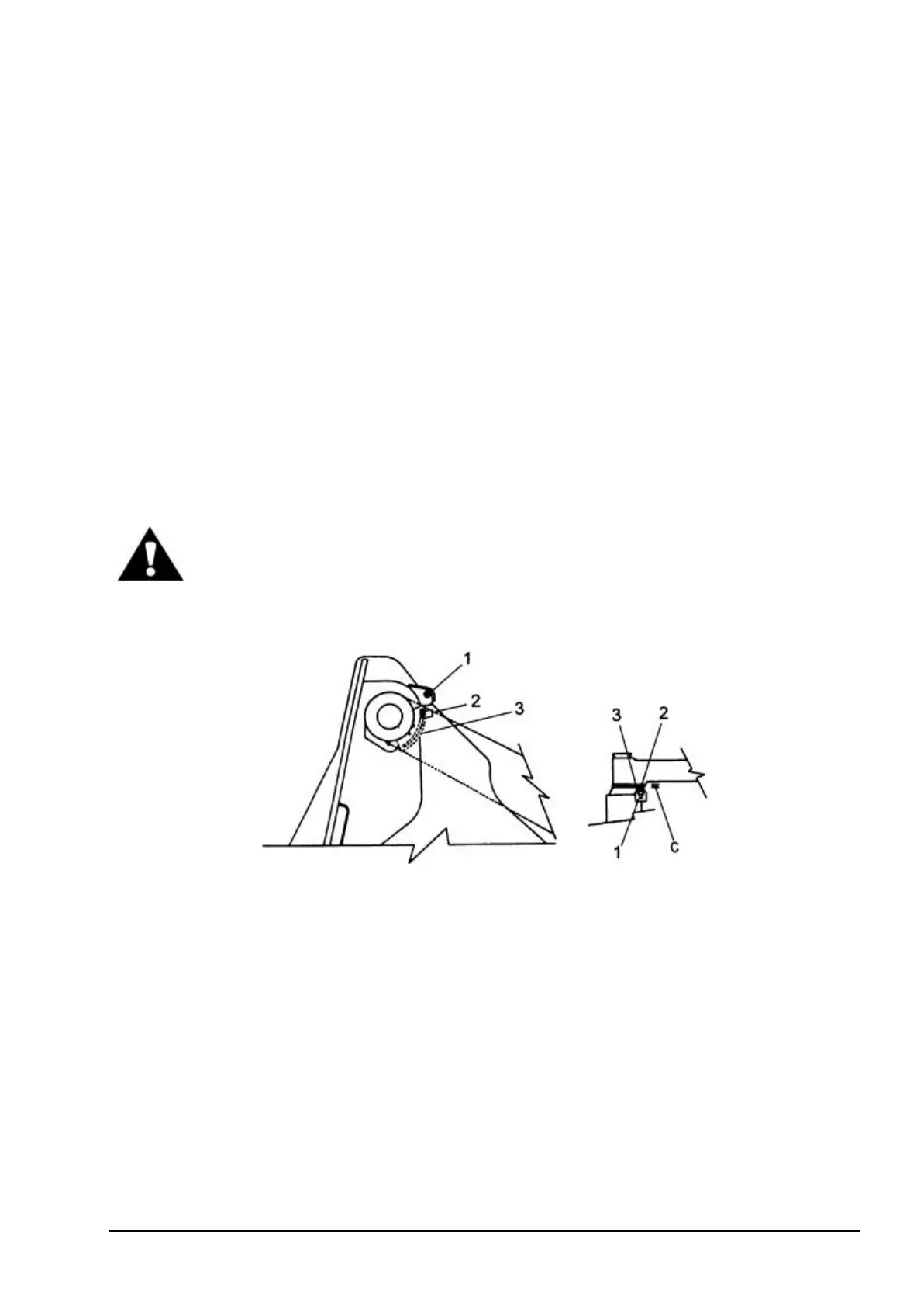
4.18.2. AUTOMATIC BOOM KICK-OUT (FIG. 4.26.)
Fig. 4.26. Automatic Boom Kick Out
1. Proximity Switch
2. Bar
3. Bracket
C – Bar-To-Switch Clearance
The electronically operated kick-out control system stops boom travel automatically at a
preselected height. This eliminates unnecessary boom travel during operation and provides for a
more efficient cycle. Proximity switch 1 is mounted to the front frame and is adjustable (in and out)
to achieve proper clearance C to bar 2. Bar 2 is slide mounted on bracket 3 and is locked in position
corresponding to the required height of the boom. The bracket is bolted to the inside of the left boom
arm up near the boom pivot. As the boom is raised to its preselected height, bar 2 has moved out of
the magnetic field of proximity switch 1, breaking the circuit. Breaking the magnetic field circuit
causes the boom control lever to move out of the detented "raise" position and into the "hold"
position, thereby stopping the travel of the boom arms. Bar-to-switch clearance C necessary for
proper operation of proximity switch is 7 mm to 8 mm.