SECTION 4 OPERATING
Page 20
OM560C99/1E DRESSTA
SUSPENSION SEAT
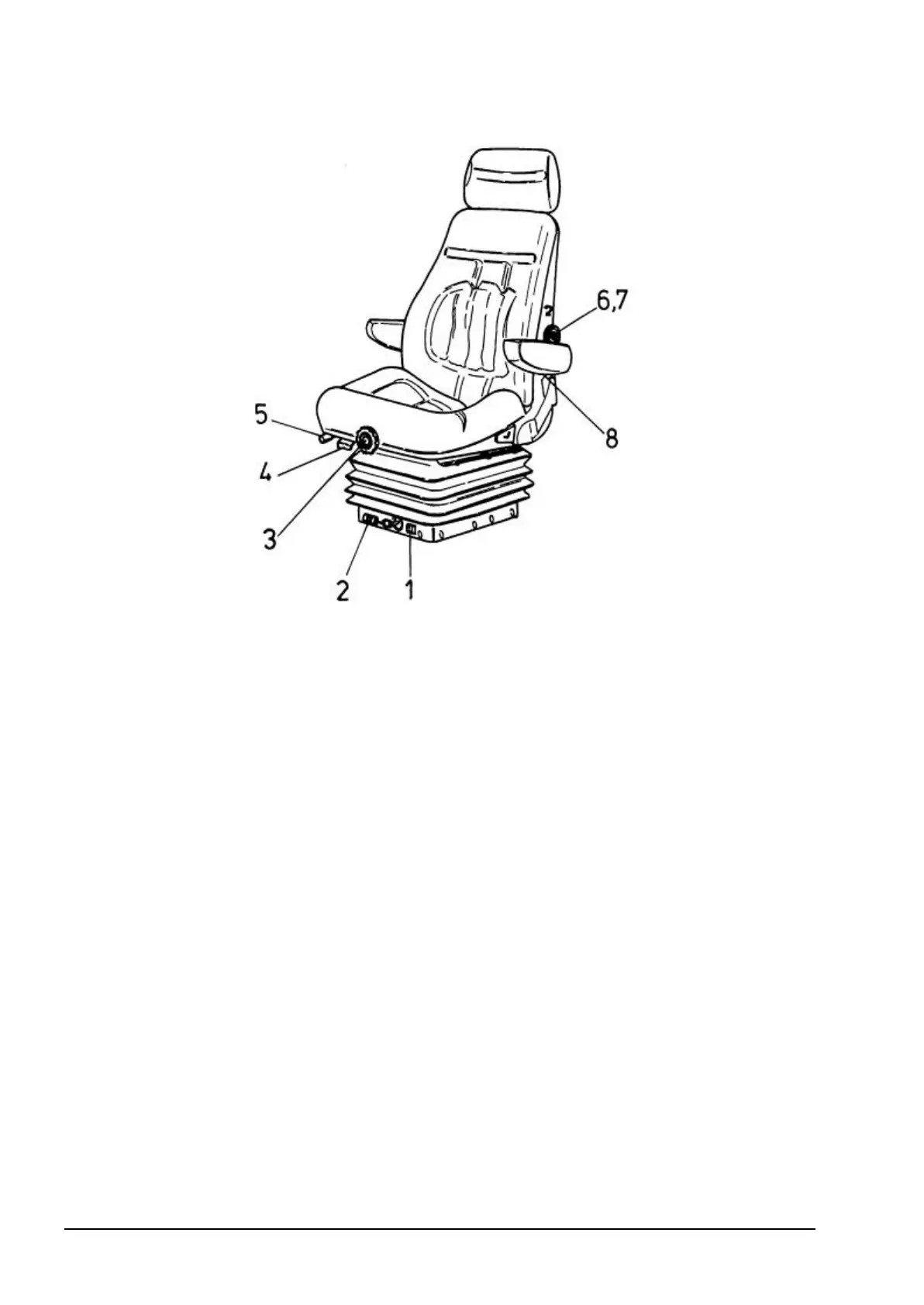
Fig. 4.9. Suspension Seat
1. Weight indicator
2. Weight adjustment knob
3. Height adjustment knob
4. Backrest angle adjustment lever
5. Seat travel lever
6. Backrest profile adjustment knob
7. Backrest profile adjustment knob
8. Armrest angle adjustment screw
This is a suspension seat with several adjustments to provide maximal comfort to the operator.
Adjustment to operator’s weight – seated in the operator’s seat turn adjustment knob (2)
clockwise or counterclockwise until proper weight value corresponding to the operator’ s weight is
in the weight indicator window 1.
Seat travel adjustment - pull up the lever 5 (on the right hand side of the seat) and slide the seat
forward or rearward to the desired position and lock with the lock lever.
Seat height adjustment - turn knob 3 clockwise to lift the seat cushion and counterclockwise to
lower the seat cushion.
Backrest angle adjustment - pull up lever 4 to release the lock. Upon adjustment of backrest
angle (pressing the backrest) apply the lock.
Backrest profile adjustment – performed with two knobs: knob 6 located on the left hand side of
the seat and knob 7 located on the right hand side of the seat. Turn knob 6 to change backrest
profile in the middle part, turn knob 7 to change lower and upper part of backrest profile.
Armrest angle adjustment – performed with screws 8 located under armrests (tilt back armrests
to facilitate adjustment).