OPERATING SECTION 4
Page 37
DRESSTA OM560C99/1E
LOADER OPERATIONS
4.18.4. AUTOMATIC BUCKET LEVELER
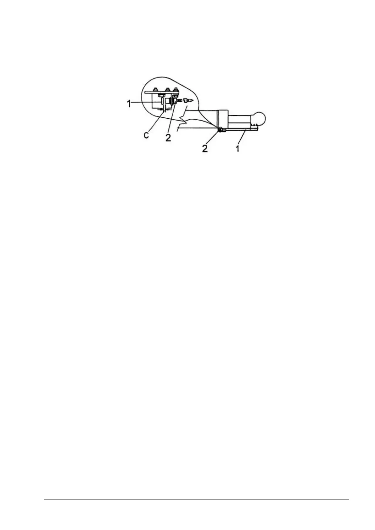
Fig. 4.28. Automatic Bucket Leveler
1. Trip Bar 2. Proximity Switch C – Bar-To-Switch Clearance
The principle of operation is as follows:
The bucket control lever may be maintained automatically in roll back position E (Fig. 4.27) with a
solenoid latch. Stopping the lever in this position is possible only when the induction proximity
switch 2 closes the circuit. When trip bar 1 attached to the bucket cylinder rod uncovers the switch,
the magnetic field is broken, solenoid latch is released which results in automatic retrun of the
bucket control lever to hold position B, Fig. 4.27. Operation of loader linkage using the leveler is as
follows. The operator after raising the boom to the required height and dumping the bucket places
the bucket control lever in roll back position E , Fig. 4.27 (detented position) and lowers the boom
with boom control lever placing it in F position, Fig. 4.27. The bucket control lever will be maintained
by the solenoid in roll back position E , Fig. 4.27 until proximity switch 2, Fig. 4.28 has been
uncovered by trip bar 1. The length of the trip bar is so selected that it will occur when the bucket is
in position prepared for the next cycle, when the bucket is in horizontal position and is resting on the
ground.
Bar-to-switch clearance C necessary for the proper operation of the proximity switch is 7 mm to 8
mm. No other adjustments are needed.
4.19. LOADER TECHNIQUES
Terrain, footing conditions, types of materials being worked and maneuvering space determine the
speed at which the loader can function. When the bucket is at work, keep the engine speed at full
throttle and operate in the first (1) gear transmission range.
Use gear range two (2) and three (3) for traveling purposes. The techniques for using the loader as
described below are not intended to be all inclusive. Each work situation will vary. Loader operation
may be altered for each particular application for its best efficiency. When possible, start all jobs
from relatively level ground. If necessary, level an area large enough to provide sufficient working
space. This prevents back and forth pitching of the loader and will result in easier operation. Avoid
wheel spin whenever possible; this wastes effort and causes ruts and piles that pitch and tilt the
loader. In cold weather, this material can freeze and cause additional difficulty the following day.
4.19.1. LOADING,TRANSPORTING AND PILING
When loading from a bank or stockpiling, use the V-method shown in Figure 4.29, or the step
loading method shown in Figure 4.30. Keep the trucks close to the work area to minimize loader
travel. Keep work areas clean and level. When possible, spot the next truck to be loaded on the
opposite side as shown in Figure 4.29.