Service Manual for Electric Convection Oven
8
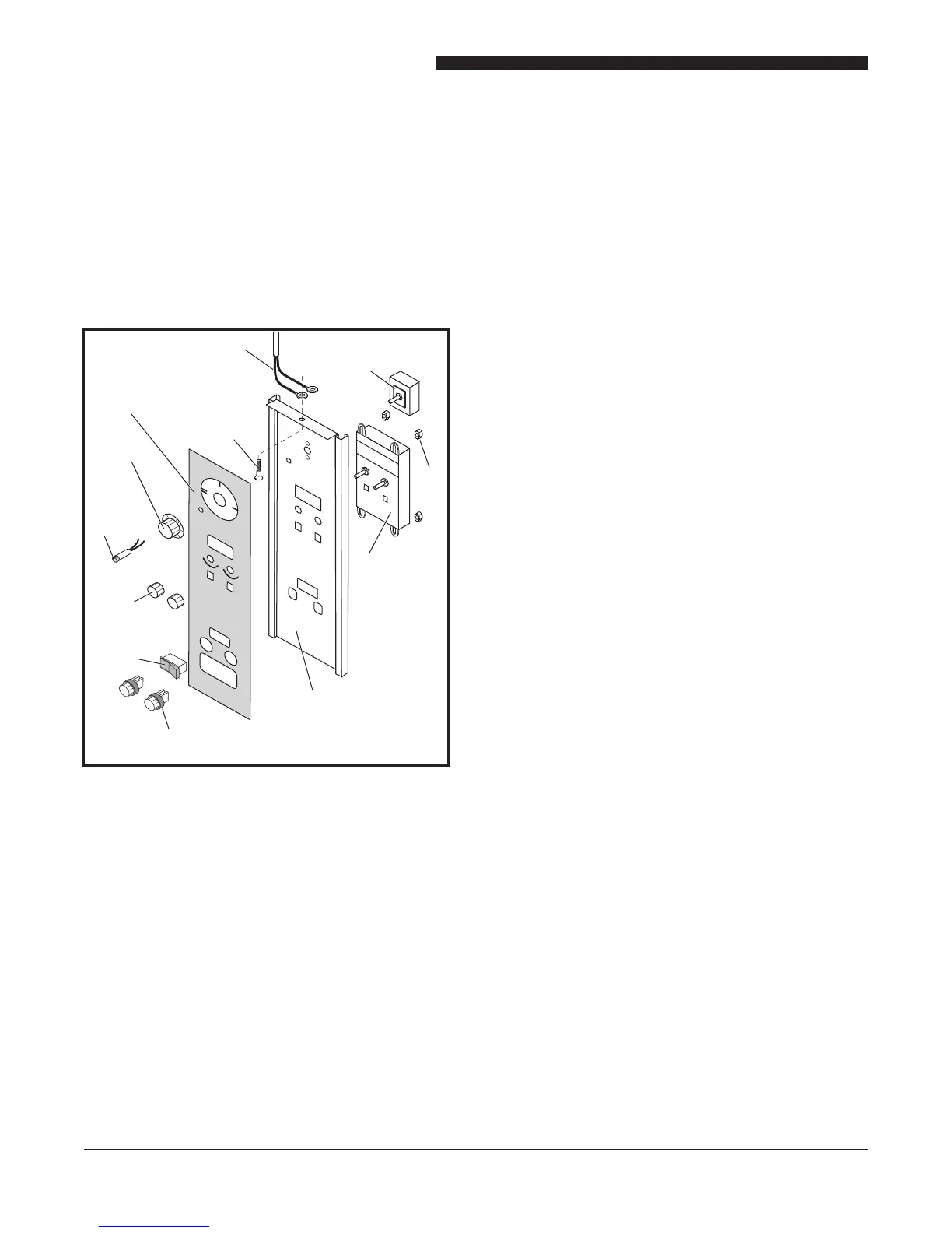
X CONTROL PANEL ASSEMBLY
WARNING: DISCONNECT OVEN FROM POWER
SOURCE BEFORE PERFORMING
ANY SERVICE.
Component Access Procedure
Remove screw at top center of X Control Panel assembly
and slide Control Panel out to allow access to Control
Panel components.
5
/
9
WARNING
Power
Switch
Nut
X Controller
Temperature
Probe
Screw
Knob
Oven
Ready
Light
Knob
Fan
Switch
Fuse Holder &
Fuse (10 amp delay)
Control
Panel
Mylar
POWER Switch
1. Perform Component Access Procedure.
2. Loosen setscrews and remove knob from POWER
Switch.
3. Tag and disconnect wires from POWER Switch.
4. Remove nut securing POWER Switch.
5. Remove POWER Switch from rear of panel.
6. Reverse procedure to install POWER Switch.
X Controller
1. Perform Component Access Procedure.
2. Tag and disconnect wires from Controller.
3. Remove knobs from front of Control Panel.
4. Remove four nuts securing Controller to Control
Panel.
5. Remove Controller from rear of Control Panel.
6. Reverse procedure to install a new Controller.
OVEN READY Light
1. Perform Component Access Procedure.
2. Tag and disconnect wires to OVEN READY Light.
3. Remove OVEN READY Light from front of Control
Panel.
4. Reverse procedure to install a new OVEN READY
Light.
Fan Switch
1. Perform Component Access Procedure.
2. Tag and disconnect wires from Fan Switch.
3. Remove Fan Switch from front of Control Panel.
4. Reverse procedure to install a new Fan Switch.
Fuse and Fuse Holder
1. Perform Component Access Procedure.
2. Remove screw (1) to access back of Control Panel
to replace Fuse Holder.
3. Tag and disconnect wires to Fuse Holder.
4. Remove nut securing Fuse Holder.
5. Remove Fuse Holder from front of Control Panel.
6. Reverse procedure to install Fuse Holder.
LIGHT Switch
NOTE: LIGHT Switch is only on the 6/13 Oven.
1. Perform Component Access Procedure.
2. Tag and disconnect wires from LIGHT Switch.
3. Remove LIGHT Switch from front of Control Panel.
4. Reverse procedure to install a new LIGHT Switch.
 Loading...