Do you have a question about the Dungs MPA 41 PF Series and is the answer not in the manual?
Identifies qualified personnel for gas safety and regulating technology.
General safety instructions and warnings to be observed during operation and handling.
Information on the correct and intended use of the device.
Potential dangers and consequences of improper use of the device.
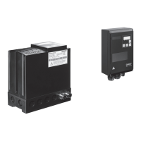
Overview of the microprocessor-controlled automatic burner control system.
Details on different models of the MPA 41xx PF available.
Information on where and how the product is used in applications.
List of certifications and approvals the product has obtained.
Electrical wiring diagram for the MPA 4112 PF model.
Electrical wiring diagram for the MPA 4122 PF model.
Explains different display modes for status, info, errors, and parameters.
Details on communication modules and tools for parameter setting.
Lists optional accessories such as flame detectors.
Provides dimensions for MPA 4112 PF and MPA 4122 PF models.
Details on protection type, temperature, voltage, power, and connections.
Part numbers and product codes for ordering different versions and accessories.
Lists certifications from CE, FM, UL, CSA, EAC, and AGA.
Details SIL, SFF, and PFH ratings for components and system.
Describes the system's suitability for high-speed burners and communication capabilities.
Lists different designations, article numbers, voltages, and displays for system variants.
Lists compatible accessories like ignition transformers and flame detectors.
Covers protection type, ambient temperature, dimensions, and weight.
Details rated voltage, frequency, fuse, isolation, power consumption, and connections.
Detailed electrical connection diagram for the MPA 4112 PF.
Detailed electrical connection diagram for the MPA 4122 PF.
Safety advice regarding handling the device and its connections.
Details functions, electrical data, and safety relevance of device outputs.
Details functions, electrical data, and safety relevance of device inputs.
Information on TWI interface, parameterization switch, and display unit inputs.
Guidance on connecting spark generators, noting no built-in transformer.
Illustrates connections for ionisation and UV flame detectors.
Describes methods for installing the MPA 4112 PF, including screw and rail mounting.
Visual representation of MPA 4112 PF dimensions with measurements.
Details direct screw connection method for installing the MPA 4122 PF.
Provides detailed dimensional drawings and measurements for the MPA 4122 PF.
Explains the functions for unlocking the device and managing access levels.
Describes functions of gas valves, air pressure switch, and HT signals.
Explains how to enter and use parameterization mode for settings.
Illustrates the operational states and transitions of the automatic system.
Explains symbols and notes used in the system operation flow chart.
Describes error states and initial operational states like switch-on delay.
Details states related to flame detection, pre-purge, ignition, and operation.
Describes states related to High Temperature (HT) mode operations and checks.
Details HT stabilization, mode, post-purge, restart protection, and safety chain states.
Explains how to change parameters, access levels, and value limits.
Configures the bus slave address for communication.
Settings for restart attempts, flame missing, and safety chain locking.
Defines operating modes for air pressure switch monitoring across different states.
Configures how the MPA handles heat requests via bus or HW input.
Defines HT mode usage, gas pressure switch, or proof of closure input.
Sets the output behavior based on different device states.
Covers safety chain duration and FM mode settings.
Defines pre-venting, pre-ignition, safety times, and stabilization durations.
Sets operation safety time and HT flame signal tolerance.
Configures after-burn time, post-venting, and restart protection durations.
Sets output functions for X14 and HT flame detection behavior.
Covers self-test, switch-on delays, and HT mode enable settings.
Defines HT transition durations and restart protection.
Sets maintenance intervals for watchdog, V1, and air output relays.
Controls HT external light monitoring and extension module configuration.
Configures priority between cooling/heating and ventilation requests.
Provides default factory settings, access levels, and value ranges for parameters.
Provides default factory settings, access levels, and value ranges for parameters.
Details status of device operation, inputs, and outputs.
Information on counters like runtime and switching cycles, and internal device status.
Displays cyclic state counter, processor load, and modulation degree information.
Explains the 3x7 segment display and the functions of the operating keys.
Describes the meaning of LED colors and the type of information displayed.
Explains how to access and use different display modes like operation, error, and info.
Provides examples of how digits and letters are displayed for status and troubleshooting.
Visual representation of the automatic system's operating states and transitions.
Instructions on how to view the state number and configure the bus address via display.
Shows how the system state is displayed during parameterization or service box checks.
Guides on accessing flame quality, runtime meters, and switching cycle counters.
Explains how error messages are displayed and acknowledged.
Instructions for accessing and viewing the last 10 recorded errors.
Explains parameter definition, timeout, and password requirements for parameterization.
Step-by-step guide for entering passwords to access parameter settings.
Illustrates the process of entering parameter values for P30, P31, P32, and P12.
Illustrates the process of entering parameters for timing and control functions.
Guides through entering parameters related to restarts, flame detection, and safety chain.
Illustrates entering parameters for air pressure switch, input modes, and controller settings.
Guides on entering output modes, restart protection, and bus address parameters.
Describes how to reset error memory, access levels, counters, and passwords.
Step-by-step process for changing service and OEM level passwords.
Lists and explains common errors indicated by flashing codes F1 through F9.
Details basic system errors, their causes, and potential remedies.
Covers further basic system errors including external application and internal errors.
Details errors related to extended functions and parameter changes.
Lists and explains errors originating from application-specific issues.
Instructions for setting the fieldbus address for device communication.
Details pin assignments for MPA 4112/4122 PF and bus termination requirements.
Configures the extension module for Profibus/Modbus and selects protocols.
Explains bus address setting, data transmission bits, and interruption handling.
Describes the format and structure of input data sent from MPA to the master.
Details the data contained in input bytes EB0 and EB1 for basic transfer.
Details the data present in the standard transfer area (bytes EB2 and EB3).
Details the data present in the extended transfer area (bytes EB4 through EB11).
Details data in the special extended transfer area (bytes EB12 through EB19).
Details interface parameters, sync/freeze modes, cycle time, and diagnosis information.
Describes Modbus output data, commands, and assigned bit functions.
Details Modbus input data registers from 0 to 4.
Details Modbus input data registers from 5 to 14.
Details Modbus input data registers from 15 to 21.
Details Modbus input data registers from 22 to 25.
Details Modbus input data registers from 26 to 37.
Details Modbus input data registers from 38 to 48.
Details Modbus input data registers from 49 to 52.
Specifies supported line lengths and baud rates for Profibus and Modbus.
Details bus termination requirements and pin assignments for communication interfaces.
Outlines operational requirements, reaction times, and signal quality evaluation for flame detectors.
Lists flame detector models released and approved by DUNGS.
Provides technical data, dimensions, and specifications for the UV 41 (HE) detector.
Guides on mounting the UV 41 (HE) detector and related precautions.
Details the specific electrical connections between the UV 41 (HE) and MPA 41xx.
Describes the DEZ ignition transformers, their technology, and applications.
Details the different DEZ transformer versions and their technical specifications.
Explains the electrical connections for the DEZ ignition transformers.
Provides dimensions for DEZ transformers and crucial safety warnings for high voltage.
Explains the purpose and use of VisionBox for accessing the MPA via PC.
| Brand | Dungs |
|---|---|
| Model | MPA 41 PF Series |
| Category | Control Systems |
| Language | English |