12 Component Information
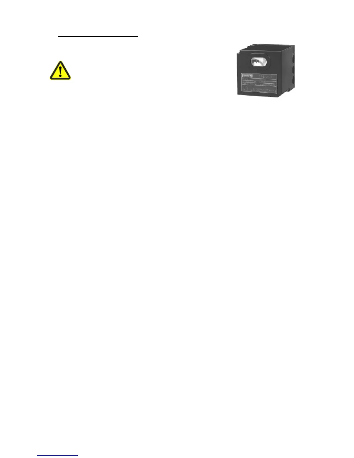
12.1 LFL1.333 Burner Control Box
To avoid injury to persons, damage to property or
the environment, the following warning notes
should be observed!
Do not open, interfere with or modify the unit!
Before performing any wiring changes in the connection
area of the LFL1…, completely
isolate the unit from the mains supply (all-polar disconnection)
Ensure protection against electric shock hazard by providing adequate protection for the
burner control’s connection terminals
Check to ensure that wiring is in an orderly state and that the wires are firmly connected
(refer to «Commissioning notes»)
Press the lockout reset button only manually (applying a force of no more than 10 N),
without using any tools or pointed objects.
Do not press the lockout reset button on the unit or the remote lockout reset button for
more than 10 seconds since this damages the lockout relay in the unit
Fall or shock can adversely affect the safety functions. Such units may not be put into
operation, even if they do not exhibit any damage.
In the case of flame supervision with UV detectors QRA..., it should be noted that sources
of radiation such as halogen lamps, welding equipment, special lamps, ignition sparks, as
well as X-rays and gamma radiation, can produce erroneous flame signals.
Mounting notes
Ensure that the relevant national safety regulations are observed.
When using 2 UV detectors QRA..., make certain that the detectors cannot see one another
Installation notes
Installation work must be carried out by qualified staff.
Always run the high-voltage ignition cables separately while observing the greatest possible
distance to the unit and to other cables.
Do not mix up live and neutral conductors
Electrical connection of ionization probe and flame detector
It is important to achieve practically disturbance and loss-free signal transmission:
Never run the detector cable together with other cables.
Line capacitance reduces the magnitude of the flame signal.
Use a separate cable of low capacitance
Observe the maximum permissible detector cable lengths (refer to «Technical data»)
2 UV detectors QRA... can be connected in parallel.
The ionization probe is not protected against electric shock hazard.
Locate the ignition electrode and ionization probe such that the ignition spark cannot arc
over to the ionization probe (risk of electrical overloads).
In connection with the QRA..., earthing of terminal 22 is mandatory.
Supervision with both ionization probe and UV detector QRA... is possible, but for safety
reasons – with the exception of the second safety time «t9» – only one flame detector may
be active at a time. At the end of the second safety time, one of the detectors must be
inactive, however, that is, the detected flame must have extinguished, e.g. by switching off
the ignition valve at terminal 17.