NOTE:
ON ANY BURNER, AN ALMOST INFINITE COMBINATION OF COMBUSTION
HEAD COMPONENTS AND SETTINGS MAY BE USED TO ACHIEVE OPTIMUM
EFFICIENCY AND A FLAME SHAPE TO SUIT A VERY WIDE RANGE OF HEAT-
RAISING APPLIANCES. THE MOST SUITABLE COMBINATION/SETTINGS
MUST BE DETERMINED DURING THE COMMISSIONING PROCEDURE.
adjustments described below, there are no pre-determined positions applicable to a particular
burner. The scale reading only represents the air damper opening and not the firing rate!
Adjustments to the burner combustion head (for example the position of the flame ring in the nose
cone) may be necessary during the `setting up` of a burner.
Details of the settings for a particular burner , firing a given make of boiler, cannot be given in a
manual of a realistic size, however, standard basic settings are given in section 3 of this manual.
The size and relative position of the flame ring to the cone will have an appreciable effect on the
volume and velocity of air passing over the flame ring and this must be taken into consideration
when setting the combustion efficiency, with adjustments made as necessary. Adjustment of the
flame plate in relation to the nose cone can be made by loosening the screws holding the nose cone
in place and moving the nose cone backwards or forwards. After adjustments have been made,
ensure that screws are retightened and sealed in place.
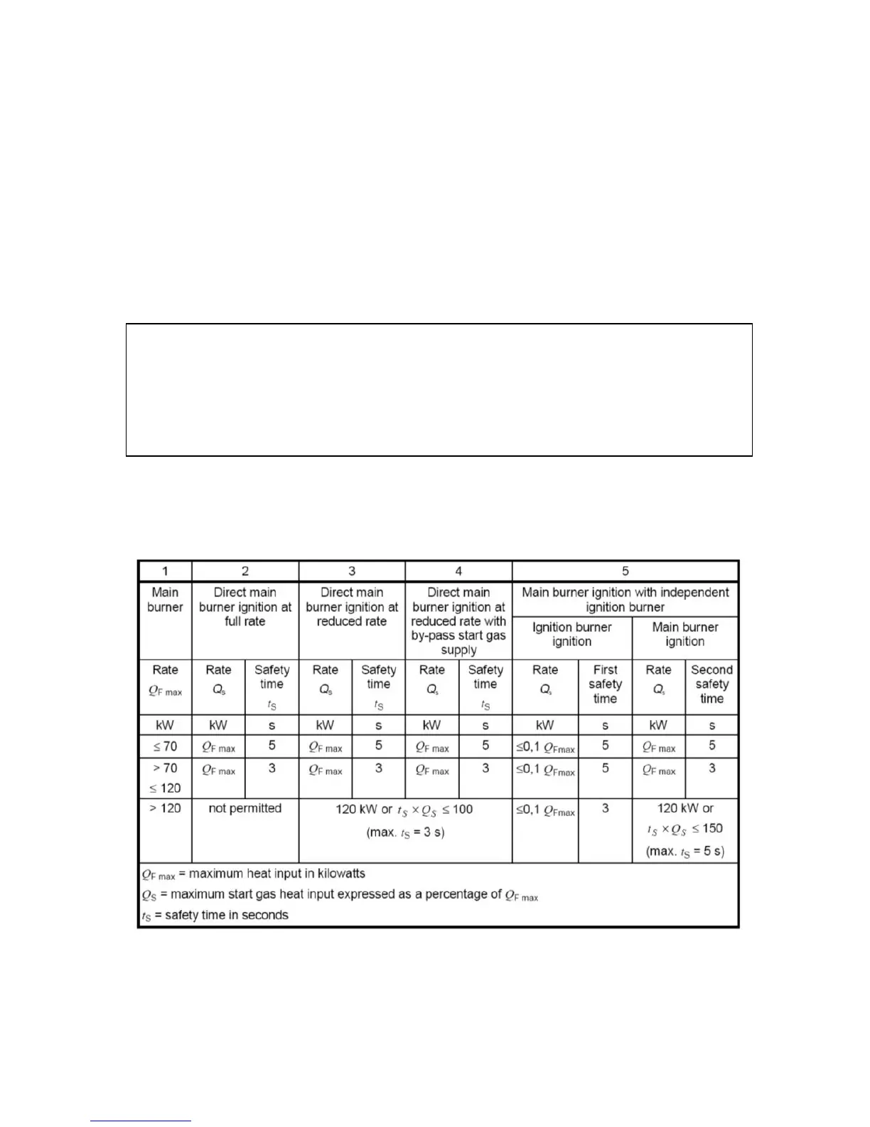
7.2 Start Gas Heat Input
The table below summarises the ignition gas rates for different burner configurations.
The start gas heat input must not exceed 120kW or the value given by the equation :
t
s
x Q
s
≤ 100
where: