Operating Instructions For TD/TAD4 Dual Fuel Burner
June 13 155 of 165 TD/TAD4 Manual Rev 4
E. The entire metering spindle and spool sleeve can be removed from the top plate. The
spindle has a Viton 'O' ring and there is a Viton 'O' ring between the cap and the valve body.
the shaft sealing is via 2 x 'O' rings which are submersed inside the spool sleeve.
There should not be any need to remove the bottom plate, although as a precautionary measure if
'O' rings are being replaced, it is good practice to replace all of the seals with the correct
specification for the valve.
12.7.5 Adjustment of the valve
Since the valve can operate either for spill back
nozzles or for direct metering of fuel, the
configuration can be changed by indexing the
pool witness mark to change the opening and
closed characteristic of the valve. In other words,
when the witness plate is indexed to position 'A'
the valve operates from closed to open over the
90 degree scale.
When the witness plate is indexed to position
'B', the valve operates from fully open to closed over a 90 degree movement. It is also possible to
change the flow characteristic of the valve by changing the position of the spool in accordance with
the details on the flow graph and scale plate indicators.
Valve adjustment is extremely simple. The design of the valve allows maximum travel from 0 to
90 degrees to control the modulating range of the burner. Depending upon the flow rate required
across the valve, this could control fuel flows in excess of 20:1 over the valve spindle angular
movement.
It is possible to adjust the output of the valve whilst still maintaining the large amount of
linearization by adjusting the spool ring on the inner scale plate. This is adjusted by loosening the
retaining cap and rotating the spool with a peg spanner. The index mark on the spool indicates the
spool position which can be read in conjunction with the flow charts on the opposite page.
12.7.6 Installation of the valve
The Variotronic valve can be mounted in any access. it is however,
essential that there is no pipe stress from either the inlet or discharge
port of the valve. Any external pressure caused from pipe stress could
distort or cause the valve to malfunction. Fixing of the valve is via a
pad with 2 off tapped holes, 5MM tapped directly into the valve body.
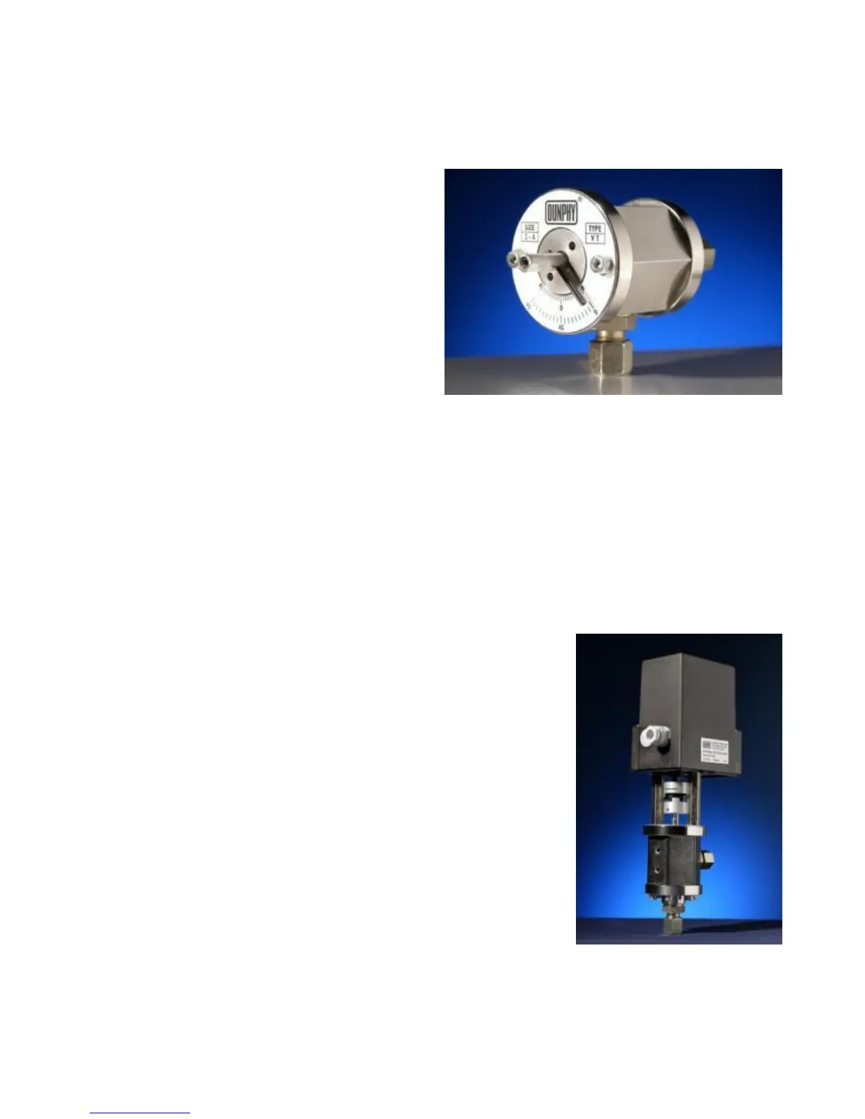
12.7.7 Valve Drive
While the Variotronic valve has primarily been designed to be driven
by an electronic positioning motor, it is possible to use the valve via
mechanical linkage. It is essential that there is zero play on any
connection between the valve spindle and the drive to the valve. This
is particularly important with electronic positioning since the valve is
normally controlled by a sensor or potentiometer mounted directly on
the servo motor shaft.
Zero hysteresis drive couplings must be used or, alternatively, a solid
coupling between the servo motor and valve spindle. Before commencing operation of the valve,
please ensure that there is oil or lubrication within the valve.
Do not run the valve dry as this could affect the long term accuracy. If the valve has to be operated
before the oil system has been fully primed, it is prudent to put lubricating oil in the valve ports.