Operating Instructions For TD/TAD4 Dual Fuel Burner
June 13 40 of 165 TD/TAD4 Manual Rev 4
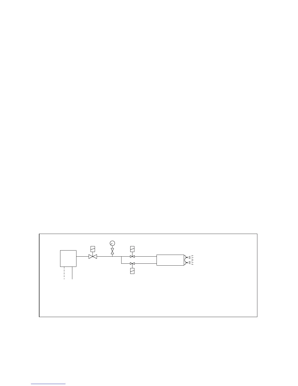
4.1.2 High / Low Oil
Atomisation of the fuel is by two separate nozzles, one for low fire and the second for high fire.
The oil supply to each nozzle passes through one of twin solenoid shut-off valves and the burner
output is determined by the size of nozzle and the pressure setting of the fuel pump regulator.
Normally, two nozzles of the same size will be used to give a total output equivalent to the
maximum continuous rating (MCR) of the appliance, and, At low fire, approximately 50% of
MCR.
Dissimilar nozzles can however be fitted to alter the low fire to high fire ratio. Nozzles of different
spray angle and patterns are used on various furnace configurations in order to give the appropriate
flame shape. The whole of the oil system is protected by a pump discharge valve ( PDV ) which is
fitted on the oil pressure outlet of the pump and which closes, isolating the oil system when the
burner is not running.
When the control box reaches the firing stage, the air damper drives to the low fire position
(CAM VI) and the ignition spark is switched on.
Both the PDV and first stage solenoid valve (V1) are energised simultaneously releasing oil
through the first stage nozzle, which is ignited by the spark from the ignition electrode.
The oil pressure should now be adjusted, by means of the pump pressure regulating screw, to give
approximately 50% of the MCR of the appliance and the air shutter adjusted to give optimum
combustion efficiency.
As the control box reaches the high fire stage, the air damper motor drives the air shutter to the
high fire position and sends a signal to the second stage oil valve (V2).
As a safety measure, the second stage oil valve is energised through an auxiliary switch in the air
damper motor (CAM VII). The logic of this arrangement is that the air damper must be in the `high
fire` position before the second stage solenoid can open, thus ensuring that an oil rich condition
cannot occur.
When a burner is switched from high to low fire, the closing speed of the solenoid will always be
faster than that of the air damper, so the combustion will again remain air-rich.
The oil pressure should now be adjusted, by means of the pump pressure regulating screw, to give
the full MCR of the appliance and the air shutter adjusted to give optimum combustion efficiency.
Nozzle throughputs are given in the table on the following page.
It is essential that, on completion, the burner is tried a number of times to ensure that changeover
between low and high fire is smooth and that the flame does not `lift off`.