Operating Instructions For TD/TAD4 Dual Fuel Burner
June 13 39 of 165 TD/TAD4 Manual Rev 4
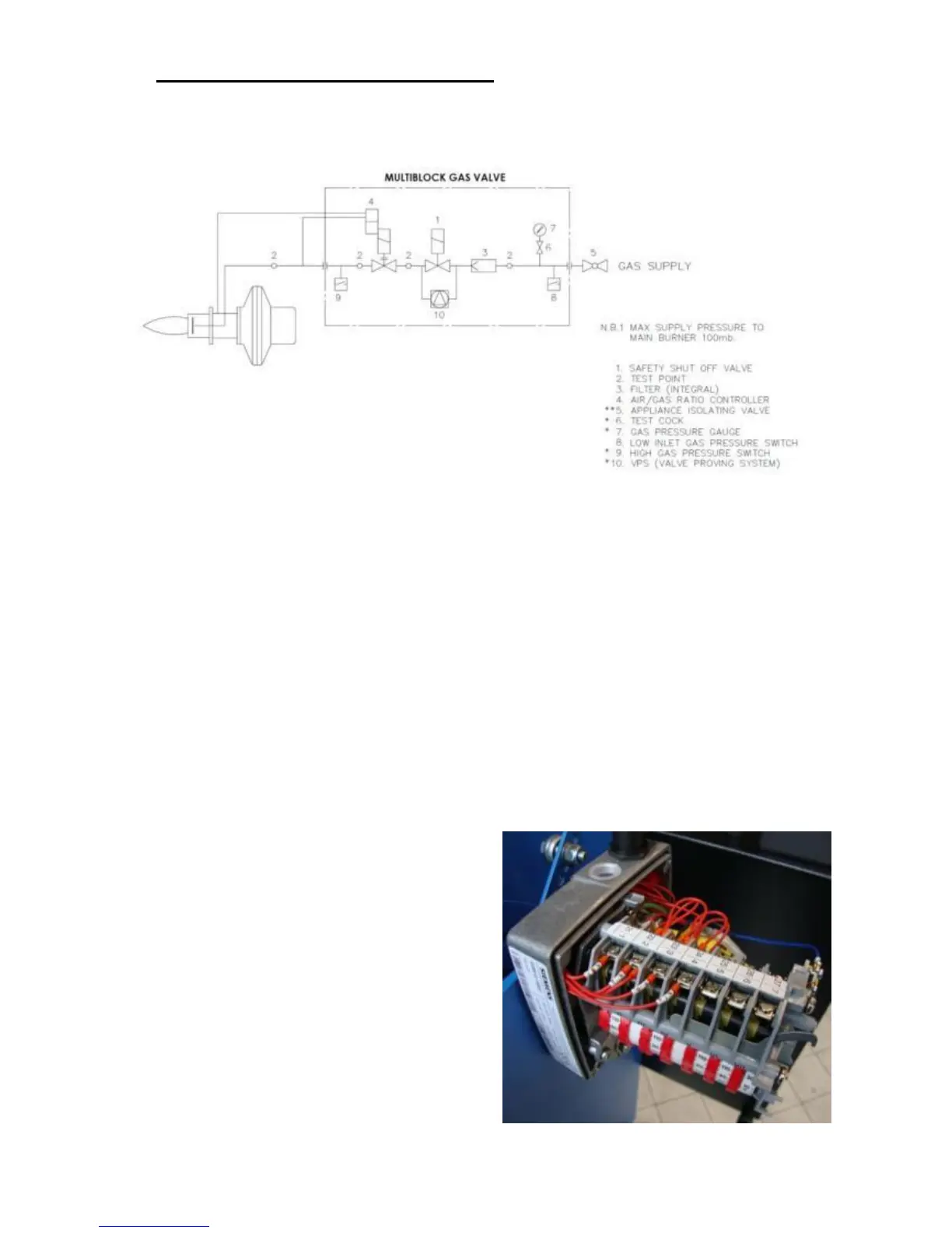
4 Adjustments and Operating Principles
4.1 High/Low burners (HL)
4.1.1 High / Low Gas
High low control is classed as the simplest form of control for a burner of this size. It relies on a
high/low thermostat monitoring either the temperature or pressure of an appliance which in turn via
the control box will drive the air damper servo between the high fire position and low fire position.
Gas regulation is performed by means of an air/gas ratio valve. The valve senses the amount of
combustion air available and regulates an internal gas governor to output sufficient gas to ensure
good combustion at both high and low firing rates. This also gives the feature of maintaining good
air gas ratio (therefore good efficiency) between high and low fire positions which wouldn’t be the
case on a standard 2 stage gas valve. When the burner is switched off the air damper will fully close
preventing any chimney buoyancy cooling of the appliance. Cam IV of the air servo motor is used
to set the ignition position of the air damper. Once the burner is lit and has stabilised the air damper
will move to either the low fire (CAM III) or high fire (CAM I) position depending on load
demand. Travel is adjusted by means of cam operated limit switches. The cam switch gears within
the motor can be disengaged by pushing the brass push button. Releasing the gears allows
adjustment of the air damper without connection to the drive unit. Adjustments of cams can be
made by hand or with the key which is housed within the motor cover.
Gas flow adjustments are made using the controls
‘V’ (for high fire adjustment) and ‘N’ (for low fire
adjustment) – see commissioning section for
details and gas valve manufacture details shown in
component section.
Cam I………... High Fire Gas
Cam II...............Air Damper Fully Closed
Cam III..............Low Fire Gas
Cam IV..... ........Ignition Position For Gas
Cam V...............High Fire Oil
Cam VI............. Low Fire Oil
Cam VII............V2 Oil