Operating Instructions For TD/TAD4 Dual Fuel Burner
June 13 79 of 165 TD/TAD4 Manual Rev 4
8.4 Dismantling and Re-assembly of Burners
Combustion Head Removal
The combustion head can be removed, as a unit, for maintenance purposes. Before commencing
refer to the combustion head drawings in the exploded diagram section at rear of this manual for
relevant positions of the various components.
(a) Open the burner, as described in the burner maintenance schedule.
(b) Disconnect the probe/HT lead and, where a UV cell is fitted, remove this from its retaining
clip and move to a safe place.
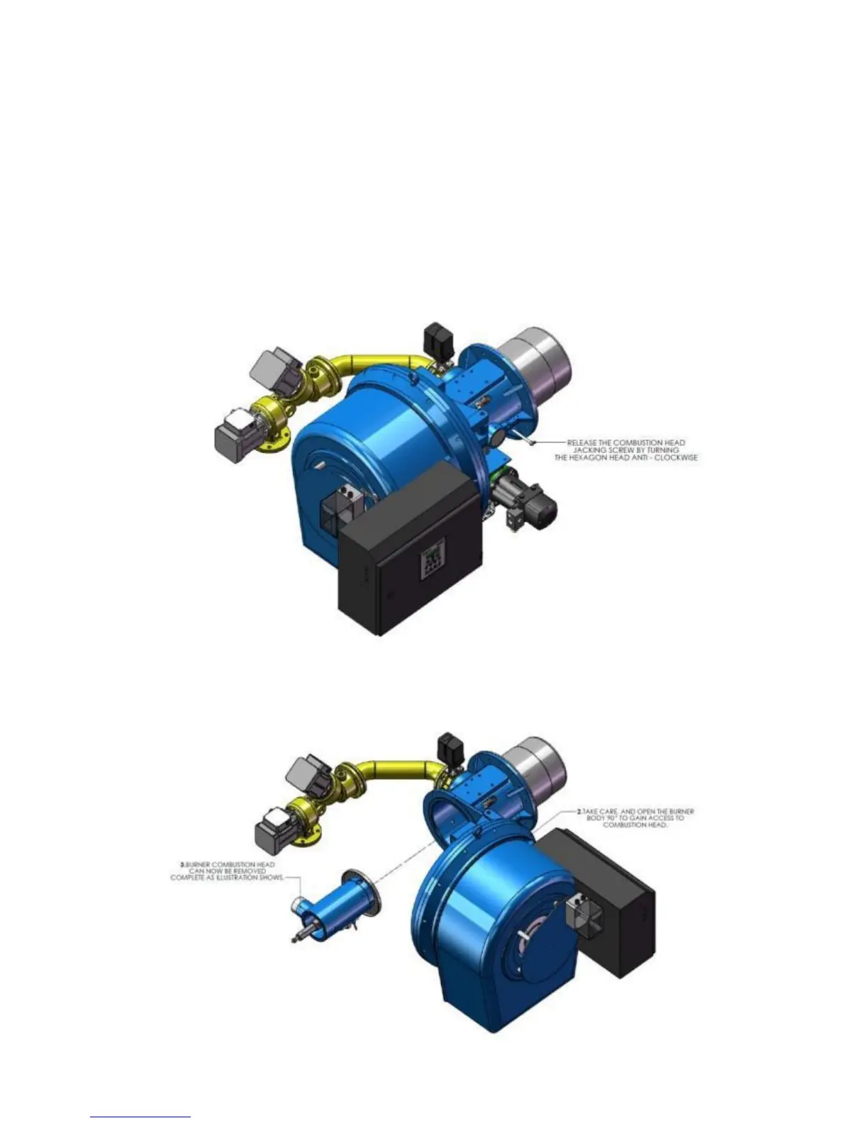
(c) Loosen the jacking screw in the mounting hinge section opposite the gas entry, as shown in
the illustration below.
(d) Pull the nozzle line spigot out of the gas entry.
(e) Withdraw the nozzle line complete, out of the blast tube.