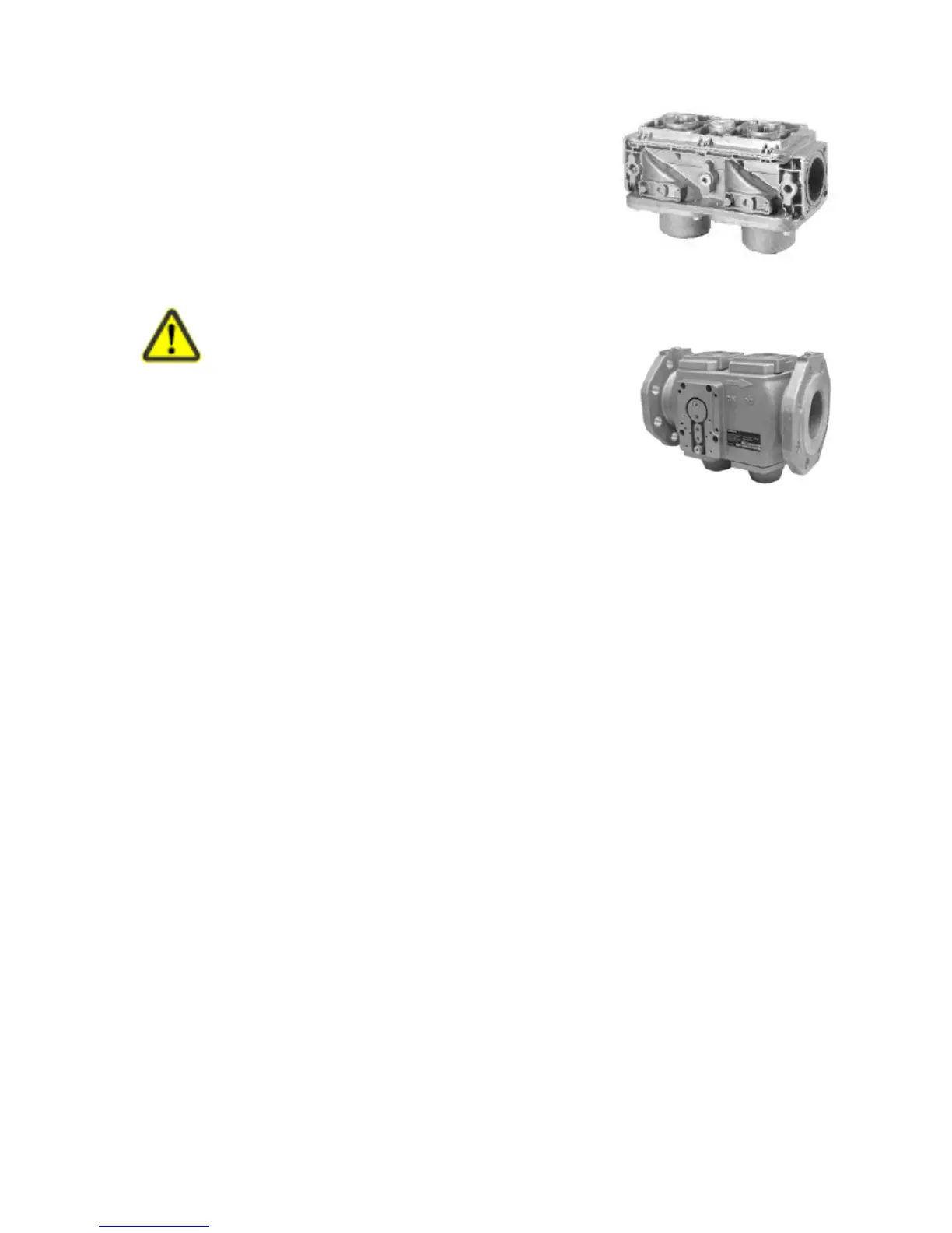
12.5 Siemens VGD20 and VGD40 Gas Valve Blocks
Double gas valves for use on gas trains, consisting of 2 class «A»
safety shutoff valves.
Suited for use in connection with gases of the gas families I...III.
The double gas valve is to be combined with 2 actuators of the
SKP… series (e.g. to provide the functions of 2 safety shutoff
valves connected in series, with different types of gas pressure
governor if required).
Supplementary data sheets on the actuators is located at the end
of this section.
To avoid injury to persons, damage to property
or the environment, the following warning notes
should be observed!
Do not open, interfere with or modify the double gas valve,
except when fitting the service replacement set! _ When used in
connection with gas, the valves constitute part of the entire safety
system. Fall or shock can adversely affect the safety functions.
Such valves may not be put into operation, even if they do not
exhibit any damage.
Protect the actuator against excessive temperatures (caused by radiation, for example), to ensure the
maximum permissible ambient temperatures will not be exceeded.
Mounting notes
Ensure that the relevant national safety regulations are complied with. To mount the double gas
valve VGD20..., 2 flanges type AGA41... / AGA51... are required.
To prevent cuttings from falling inside the valve, first mount the flanges to the piping and then
clean the associated parts. On the gas train, the valve can be mounted in any position, but the
permissible mounting positions of the associated actuator must be observed (refer to the relevant
Data Sheet)
The direction of gas flow must be in accordance with the arrow on the valve body.
When used in combination with the SKP10..., SKP15..., SKP25... or SKP75...,
the minimum gas pressure switch must always be mounted upstream of the double gas valve!
The electro hydraulic SKP15... actuator, which is used for shutoff functions, must always be
mounted on the inlet side while the actuators with integrated governor (SKP25..., SKP75...,) must
always be fitted on the outlet side of the valve (with a contoured disk).
Check to ensure the bolts on the flanges are properly tightened . Check to ensure the connections
with all components are tight. Mounting and replacement of the actuator can take place while the
valve is under pressure. Sealing materials are not required. Ensure that the O-rings are fitted
between the flanges and the valve body.
Installation notes
Installation work must be carried out by qualified staff.
If the available gas pressure exceeds the valve’s maximum permissible operating pressure, the gas
pressure must be reduced by a pressure regulator upstream of the valve.