Operating Instructions For TD/TAD4 Dual Fuel Burner
June 13 19 of 165 TD/TAD4 Manual Rev 4
2 Installation
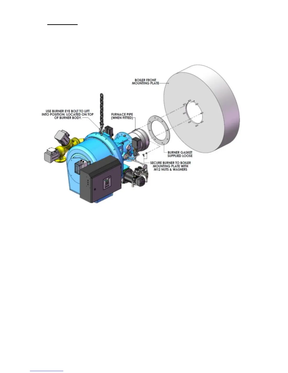
2.1 Burner Mounting
Care must be taken when mounting the burner not to damage the mounting gasket. The furnace
pipe (where fitted) is generally positioned at 12 o’clock on the mounting flange and care must be
taken not to damage it during the mounting process.
Note: - Ensure that the burner mounting gasket is correctly fitted when fixing the burner to
the appliance. This gasket creates a gas-tight seal between the boiler and burner and also
insulates the burner mounting casting.
It is important to check that the burner draught tube projection into the combustion chamber
conforms to the appliance manufacturers instructions.
Non standard draught tube projections are available on request; - please consult the Dunphy sales
dept.
In general, for reverse flame boilers the draught tube projection into the combustion chamber
should be between 50 and 100mm. For other boilers the burner draught tube should finish flush or
slightly proud of any boiler refractory or insulation. Low NOx heads should be projected into the
furnace by at least 100 - 150mm.
If there is any doubt about the correct projection into the combustion chamber, the appliance
manufacturer must be consulted.