Operating Instructions For TD/TAD4 Dual Fuel Burner
June 13 38 of 165 TD/TAD4 Manual Rev 4
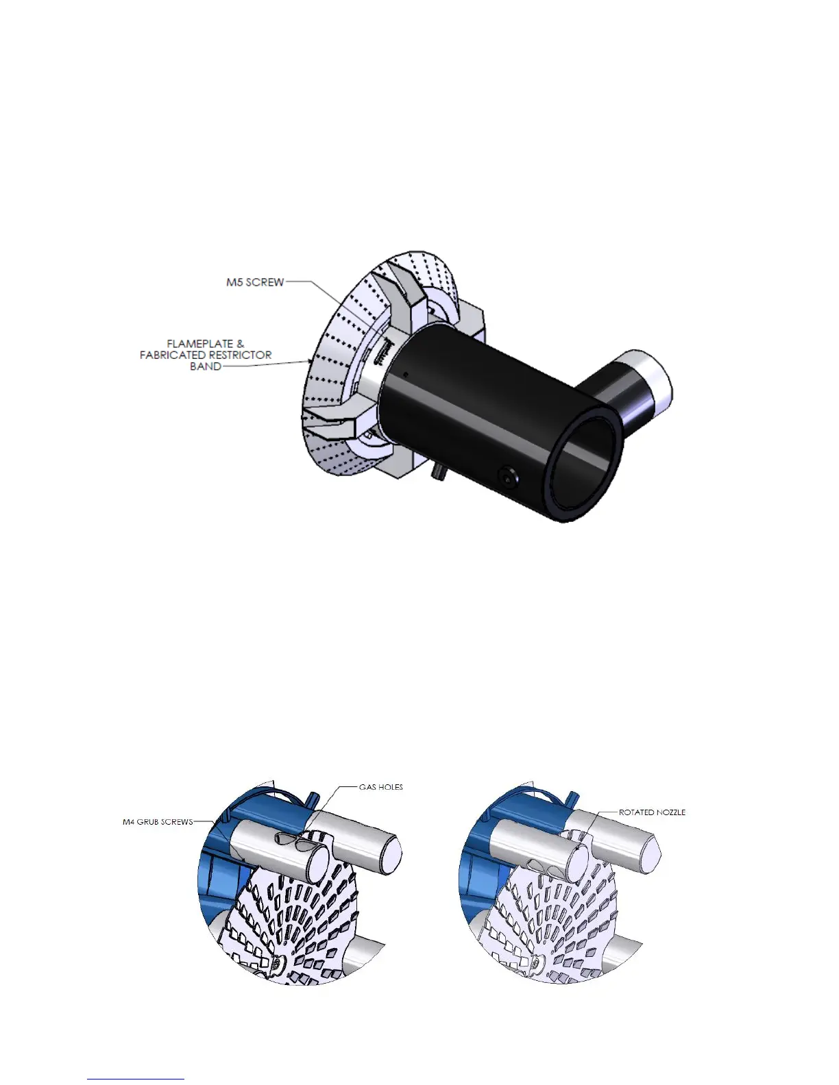
3.3 Nozzle Adjustment
3.3.1 Gas Head
The Combustion head is attached to the gas inlet on the body. The gas flows through the gas annulus
and through the 4 holes in the gas nozzle.
The gas flow can be altered by adjusting the restrictor band, shown below. Undo the four M5 screws,
rotate the band to open or close the nozzle holes.
3.3.2 Multipipe Gas Nozzle adjustment
The Combustion head is attached to the gas inlet on the body. The gas flows through the 6 gas pipes and
through the holes in the gas nozzles.
The gas flow can be altered by rotating the nozzles to direct the gas either towards or away from the
centre of the burner.
The gas nozzles can also be adjusted along the multipipe head, this will either move the gas holes closer
or further away from the flameplate.
To carry out the above adjustments, loosen the 2x M4 grub screws on each nozzle securing the nozzle
to the pipe.