10
2. INSTALLING THE UNIT
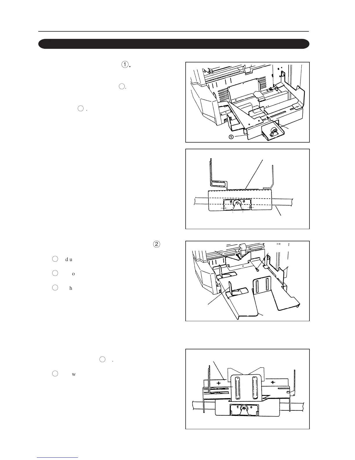
1 Attach the jogger unit
ó
.
Remove the two ornamental screws attached to the
unit and attach the jogger unit
ó
.
<Parts Used>
Jogger unit
ó
................................. 1
• Screw on the stopper screws lightly and push
down the left and right edges of the jogger unit
equally so that it does not tilt as shown in the
figure. Then tighten the stopper screws firmly.
2 Attach the paper receiving table
ò
.
ó
Adjust the left jogger to the B4 mark and move the
right jogger to the right completely.
ò
Remove the two stopper screws attached to the
unit.
ô
Push the back jogger of the paper receiving table
in the direction of the arrow so that the paper
receiving table runs onto the jogger unit.
Note
If the back jogger moves to and fro when you move the
paper receiving table to the left and right with your
hand, it indicates that the table has been attached
properly.
<Parts Used>
Paper receiving plate
ò
................. 1
ö
Screw on the stopper screws lightly and push
down the left and right edges of the paper
receiving plate equally so that it does not tilt as
shown in the figure. Then tighten the stopper
screws firmly.
2-3. ATTACHING THE PARTS
Paper receiving table
Back jogger
Set screw
Jogger (right)
Paper receving table
Jogger (left)
Jogger unit
Reinforcement Plate (lower)
Jogger unit
Ornamental
screws