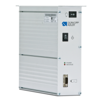
1. Insert the plugs for the individual components into the
Front side Rear side Plugs
①
②
③
④
⑤
⑥
⑦
⑧
⑨
⑩
⑪
⑫
⑬
⑭
⑮
⑯
⑰
(1) - Switch for sewing lamp
(2) - Switch for power supply
(3) - External synchronization
(4) - Status LEDs
(5) - Connection for machine upper
section
(6) - Connection for backup dongle
(7) - Connection for sewing motor
(8) - Connection for sewing motor
encoder
(9) - Connection for control panel
(10) - Connection for foot pedal
(11) - Machine identification
(12) - Plug for sewing motor
(13) - Plug for sewing motor encoder
(14) - Plug for control panel
(15) - Plug for footpedal
(16) - Plug for machine upper section
(17) - Plug for machine identification