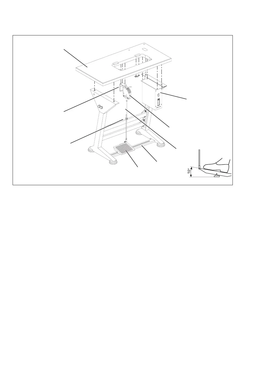
4.3 Fitting the pedal
–
Attach the pedal 5 to the stand brace 4.
–
For ergonomic reasons align the pedal 5 as follows:
The center of the pedal must be approximately under the needle.
There are slots in the stand brace 4 to help align the pedal.
–
Screw the ball pins from the middle to the front hole in the lever.
–
Hinge the pedal linkage 3 with the ball sockets on the set value
initiator 2 and into the pedal 5.
–
Loosen screw 6.
–
Adjust the height of the pedal linkage 5 as follows:
when released the pedal 4 should be at an angle of about 10°.
–
Tighten screw 6.
4.4 Fitting the set value initiator
–
Screw L-bracket 7 under the table plate 8.
–
Screw the set value initiator 2 onto the L-bracket 7.
10
1
8
2
5
7
6
3
4
 Loading...