3 Assembling the stand
3.1 Assembling the stand components
–
Assemble the individual stand components as shown in the
illustration.
–
Adjust the set screws 8 to insure the stability of the stand.
Make sure that the stand is safe by insuring that every single foot
of the stand touches the ground.
3.2 Assembling the table plate
In order to have an optimal arrangement of the components, follow the
layout.
Stand Layout
MG55 400304 0791 867710
MG55 400314 0791 867711
–
Screw the drawer 10 with its holders onto the left side underneath
the table plate.
–
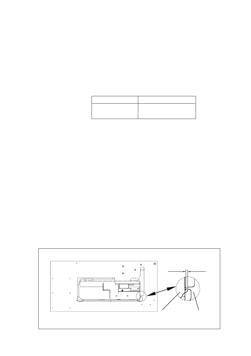
Screw the oil sump 7 under the table plate.
With sewing machine equipped with direct drive, all the three stops
should lie against the table opening.
With sewing machine equipped with the drive mounted under the table,
the stop 14 must have 9 mm distance from the table top opening.
–
Screw the main switch 5* to the right side under the table plate.
–
Screw the cable duct 4* behind the main switch 5 under the table
plate.
–
Screw the holder 3 for the traction relief of the connecting cable
behind cable duct 4 under the table plate.
–
Screw the sewing-lamp transformer 6 (optional equipment)
under the table plate.
–
Put the cap 13 into the bore hole of the table plate.
–
Place the hinge bottoms 12 for the machine head into the cutout
of the table plate 9 and tighten the screws.
–
Insert the rubber corner 2.
–
Attach the table plate 11 to the stand with woodscrews (B8 x 35)
(see sketch for position).
–
Insert the yarn stand 1 in the hole in the table plate and secure it with
the nuts and washers. Fit and align the yarn reel and unwinding holders.
The yarn reel holder and the unwinding arm must be vertically in line.
–
Screw the holder for the oil-can 9 onto the left-hand stand brace.
* Not applicable with sewing machines with direct drive.
9mm
oil sump table plate
DRIVE UNDER THE TABLE
7
3 Assembling the stand
3.1 Assembling the stand components
–
Assemble the individual stand components as shown in the
illustration.
–
Adjust the set screws 8 to insure the stability of the stand.
Make sure that the stand is safe by insuring that every single foot
of the stand touches the ground.
3.2 Assembling the table plate
In order to have an optimal arrangement of the components, follow the
layout.
Stand Layout
MG55 400304 0791 867710
MG55 400314 0791 867711
–
Screw the drawer 10 with its holders onto the left side underneath
the table plate.
–
Screw the oil sump 7 under the table plate.
With sewing machine equipped with direct drive, all the three stops
should lie against the table opening.
With sewing machine equipped with the drive mounted under the table,
the stop 14 must have 9 mm distance from the table top opening.
–
Screw the main switch 5* to the right side under the table plate.
–
Screw the cable duct 4* behind the main switch 5 under the table
plate.
–
Screw the holder 3 for the traction relief of the connecting cable
behind cable duct 4 under the table plate.
–
Screw the sewing-lamp transformer 6 (optional equipment)
under the table plate.
–
Put the cap 13 into the bore hole of the table plate.
–
Place the hinge bottoms 12 for the machine head into the cutout
of the table plate 9 and tighten the screws.
–
Insert the rubber corner 2.
–
Attach the table plate 11 to the stand with woodscrews (B8 x 35)
(see sketch for position).
–
Insert the yarn stand 1 in the hole in the table plate and secure it with
the nuts and washers. Fit and align the yarn reel and unwinding holders.
The yarn reel holder and the unwinding arm must be vertically in line.
–
Screw the holder for the oil-can 9 onto the left-hand stand brace.
* Not applicable with sewing machines with direct drive.
9mm
oil sump table plate
DRIVE UNDER THE TABLE
7