12
12
12
12
CAN
CAN
CAN
CAN bus
bus
bus
bus
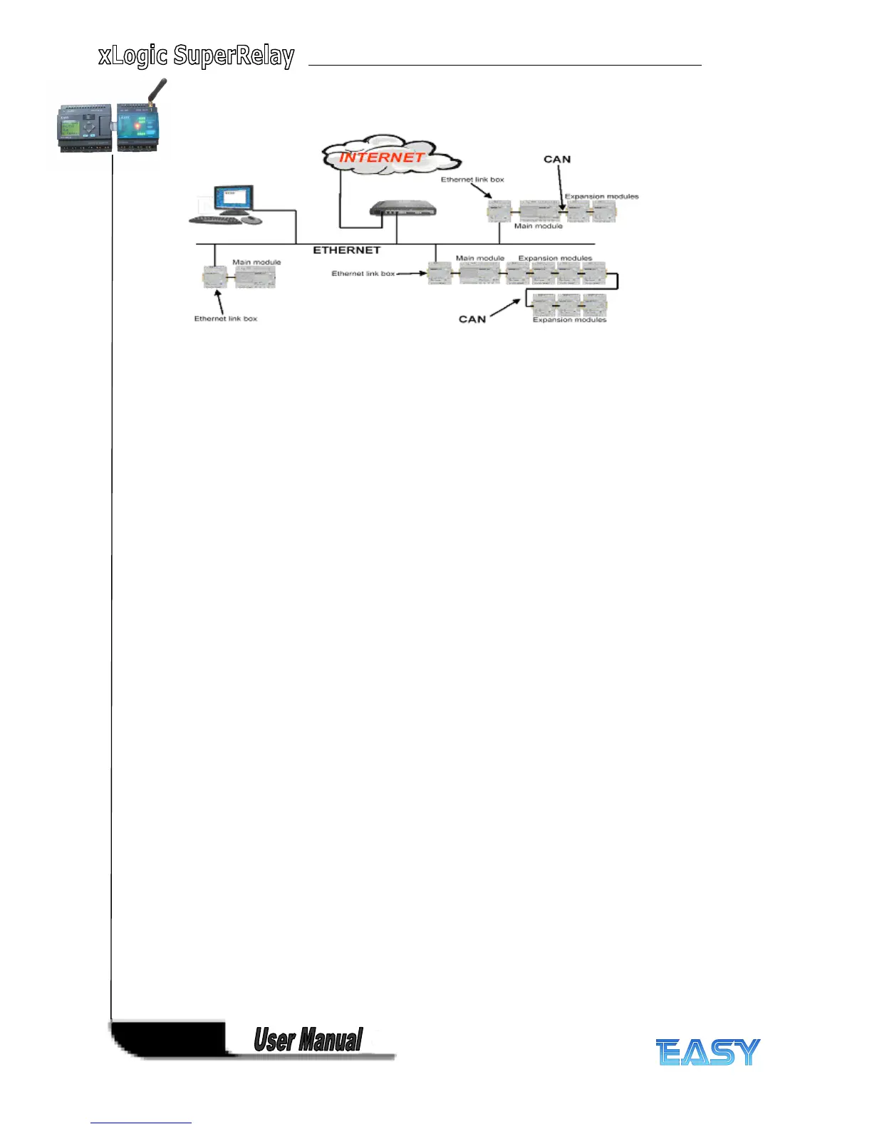
The communication between the main module and the expansion modules or the remote I/O
happens over a CAN bus. CAN is a widely used bus system ( only ELC-18 Series available, not
applied to ELC-12 series )
Note
Note
Note
Note
xLogic Main Module may be equipped with expansion mod ules of the different voltage class, but
expansion module must be supplied the correct power corresponding to its type.
Each xLogic Main Module provides the followin g connections for the creation of the circuit
program, regardless of the num ber of connected blocks:
Digital inputs I1 to IC ( ELC-18 ) , I1 to I8(ELC-12).
Analog inputs AI1 to AI8
Digital outputs Q1 to Q6 ( ELC-18 ) , Q1 to Q4(ELC-12)
Digital flag blocks F1-F64(applied to standard ELC-12&Upgraded ELC-18 CPU) ;
F1-F32(applied to other ELC series CPU)
-F8 : Startup flag
Analog flag blocks A F 1 to A F 6 4(applied to standard ELC-12&Upgraded ELC-18 CPU);
AF1-AF32(applied to other ELC series CPU)
Shift register bits S1 to S8
4 cursor keys