73
73
73
73
Timing
Timing
Timing
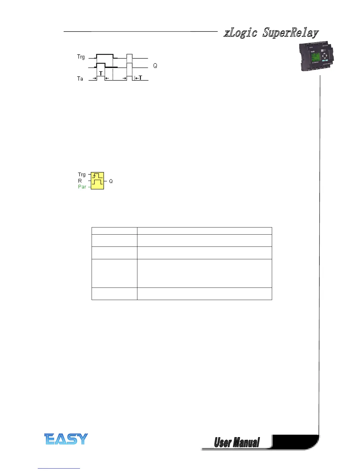
Timing diagram
diagram
diagram
diagram
Description
Description
Description
Description of
of
of
of the
the
the
the function
function
function
function
With the input signal Trg = 1, output Q is set to 1. The signal also triggers the time Ta, while the
output remains set.
When Ta reaches the value defined at T (Ta=T), the output Q is reset to 0 state (pulse output).
If the signal at input Trg changes from 1 to 0 before this time has expired, the output is
immediately reset from 1 to 0.
4
4
4
4 .4.6
.4.6
.4.6
.4.6 Edge
Edge
Edge
Edge triggered
triggered
triggered
triggered wiping
wiping
wiping
wiping relay
relay
relay
relay
Short
Short
Short
Short description
description
description
description
An input pulse generates a preset number of output pulses with a defined pulse/pause ratio
(retriggerable), after a configured delay time has expired.
Parameter
Parameter
Parameter
Parameter
The pulse width TH and the interpulse width TL can be provided by the actual value of another
already-programmed function:
Analog comparator: Ax – Ay
Analog trigger: Ax
Analog amplifier: Ax
Analog multiplexer: AQ
Analog ramp: AQ
Analog math: AQ
PI controller:AQ
Data latching relay: AQ
Up/Down counter: Cnt
Connection
Connection
Connection
Connection Description
Description
Description
Description
Input Trg
Trg
Trg
Trg You trigger the times for the Edge-triggered wiping relay
with a signal at input Trg (Trigger).
Input R
R
R
R The output and the current time Ta are reset to 0 with a
signal at input R.
Parameter TL,
TL,
TL,
TL, TH:
TH:
TH:
TH: The interpulse period T
L
and the pulse period T
H
are
adjustable.
N
N
N
N determines the number of pulse/pause cycles T
L
/ T
H
:
Value range: 1...9.
Retentivity
Retentivity
Retentivity
Retentivity set (on) = the status is retentive in memory.
Output Q
Q
Q
Q Output Q is set when the time T
L
has expired and is reset
when T
H
has expired.