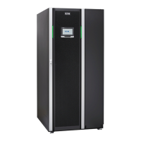
3.5.2 93PM 200 kW SIAC-MBS
The side integrated accessory cabinet (SIAC-MBS) for 160-200 kW 93PM
includes a mechanical maintenance bypass switch and 1 or 2 input breakers for
dual or single feed installation.
3.5.3 Top air exhaust kit
The top air exhaust kit is used to direct the UPS cooling air front-to-top. The kit
will eliminate the cooling clearance requirement from the back of the unit, and
enable installing the UPS even against a wall, in a corner or back-to-back. The
kit increases the depth of the unit by 200 mm.
Refer to Section
4.3
for further information.
3.5.4 Top cable access kit
The top cable access kit is designed to support top cabling to the 30-150 kW
93PM UPS in sites where the cabling is distributed through overhead cable
trays. The kit is installed at the right hand side of the UPS unit.
The 200 kW 93PM UPS does not require this kit, since the unit supports bottom,
rear, and top cable entry by standard.
Refer to Section
4.3
, Section
5.1
and Figure
14
for further information.
3.5.5 Single feed kit
The Eaton 93PM UPS is configured for dual feed by standard, requiring a
separate feed for rectifier and static bypass input. Single feed kits are available
for 80–200kW models for on-site installation. In addition, a single feed
configuration can be fitted to the 30–50kW models using jumper-cables during
installation.
3.5.6 Separate battery option
By standard, the Eaton 93PM UPS has one external battery connection, through
which external batteries supply all UPMs. If needed, the external battery
connections can be ordered as a separate battery configuration for the multi-
modular 80–200kW models. This option enables connecting a separate external
battery to each 50 kW UPM. See Section
5.4.1
for more information.
3.5.7 Field Installed UPM
A Field Installed UPM (F-UPM) can be installed in the cabinet any time in the
future when power needs change. This enables the UPS system to grow with
the business, thus lowering the initial investment necessary for the system on
day one.
Eaton 93PM UPS 30–200 kVA
User's and installation guide
©
Eaton Corporation plc 2017. All rights reserved. Revision: 005 Document ID: P-164000249 30 (126)

 Loading...


