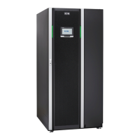
These instructions guide the installation of the device with SIAC-MBS.
1. Remove the front plate of the integrated accessory cabinet (finger screw on
the top of the plate).
2. Remove dead-front screws and dead-front.
3. Remove the applicable plates for cable installation access. You can install
the power wiring through the rear, bottom or top of the cabinet. See Figures
18
and
19
.
4. Drill or punch holes for the cable glands on the plate used for cable entry.
5. Install suitable cable glands on the plate.
6. Route all the cables through wire way to the UPS terminal block.
7. Reinstall wire entry plate and install conduit if needed.
8. Connect power wiring to the terminals and tighten to the right torque. See
Table
14
and Figures
16
and
17
.
9. When all wiring is complete, reinstall the safety shield panels. Make sure
that the handle in the dead front is in the same position as the switch when
reinstalled.
10. Install the front plate and tighten the finger screw on the top of the front
plate.
Table 14: UPS power cable terminal torques (93PM 160-200 kW)
Function Tightening torque [Nm] Bolt size
L1, L2, L3, N 80 M12
PE (ground) 47 M10
Eaton 93PM UPS 30–200 kVA User's and installation guide
©
Eaton Corporation plc 2017. All rights reserved. Revision: 005 Document ID: P-164000249 59 (126)

 Loading...


