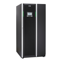
Figure 17. 200 kW SIAC-MBS connector locations (2 breaker dual-feed version)
1
Bypass input breaker 10 X3: Rectifier input L1
2 Rectifier input breaker 11 X3: UPS output N
3 Maintenance bypass switch 12 X3: UPS output L3
4 X1: Neutral & X2: Neutral for rectifier and
bypass inputs
13 X3: UPS output L2
5 X2: Bypass input L3 14 X3: UPS output L1
6 X2: Bypass input L2 15 External battery BATT+
7 X2: Bypass input L1 16 External battery BATT-
8 X3: Rectifier input L3 17 Ground
9 X3: Rectifier input L2
Figure 18. 93PM 200 kW SIAC-MBS gland plate locations (top and bottom)
1
Cable access gland plate
Eaton 93PM UPS 30–200 kVA User's and installation guide
©
Eaton Corporation plc 2017. All rights reserved. Revision: 005 Document ID: P-164000249 61 (126)

 Loading...


