04/10 MN04020001Z-EN
Parameter menu (PAR)
97
Heat protection of the motor (P8.6 – P8.9)
The temperature model is based on the assumption that the motor
achieves a winding temperature of 140°C at rated speed and an
ambient temperature of 40 °C, with 105 % rated load.
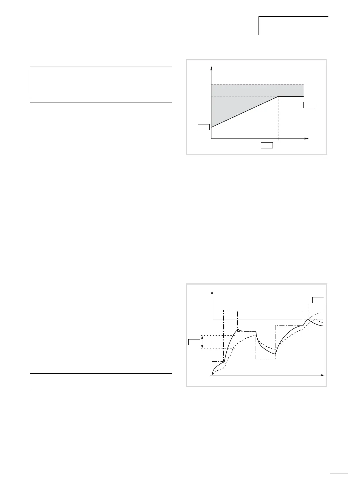
The cooling efficiency, without external cooling, is a function of
the speed (corresponding with the output frequency of the
frequency inverter). When the motor is stationary (zero frequency),
heat is also dissipated through the housing surface.
When the motor is under a great load, the current required by the
motor can be higher than the rated operational current. The
current provided by the frequency inverter can be higher than the
rated operational current of the motor. If the load requires this
much current, there is a danger of a thermal overload. This is
especially the case at lower frequencies (< 25 Hz). Here, the
cooling effect (speed of the motor fan) and the load rating of the
motor (see data sheet of the motor) are reduced similarly with
lower frequencies. On motors that are equipped with an external
fan, there is less of a load reduction at lower speeds.
With parameters P8.6 to P8.9, a motor temperature protection can
be set for the frequency inverter M-Max
TM
which protects the
motor from overheating. The temperature protection is calculated.
A direct temperature measuring in the windings of the motor (see
thermistor protection) offers great protection.
The reaction of the M-Max
TM
frequency inverter to a detected
thermal overload can be set via parameter P8.6. At parameter
P8.8 you can set the cooling output (P
Cool
) on the motor at zero
frequency (standstill). Note here the specifications of the motor
manufacturer.
Possible setting values are 0 to 150 % of the cooling output at the
rated frequency f
N
(see nameplate of the motor = P7.6).
The thermal current I
th
corresponds with the load current at
maximum thermal load rating on the motor. In continuous
operation, at rated frequency (f
N
= P7.6) and rated loading, the
value of I
th
corresponds with the rated operational current of the
motor (see rating plate of the motor = P7.1).
The time constant for the motor temperature (P8.9) defines how
long it takes until the temperature has achieved 63% of its end
value in the motor. In practice, this temperature time is constant
depending on the type and design of the motor. It varies between
the different design sizes at the same shaft power and between
the different motor manufacturers.
The larger a motor is, the greater the time constant.
The factory set value (P8.9 = 45 min) can be set in the range
between 1 and 200 minutes. The guide value is twice time t
6
of a
motor. The t
6
time defines the time in seconds in which a motor
can be operated safely at six times the rated operational current
(for this see data sheet of the motor, manufacturer specifications).
If the drive is stopped, the time constant is increased internally to
three times the set parameter value (P8.9).
h
The motor temperature protection is based on a
calculated temperature model and uses the motor current
set in parameter P7.1 to determine the motor load. It does
not use a temperature measurement in the motor.
h
Caution!
Debounced inputs may not be used in the safety
circuit diagram.
The calculated temperature model cannot protect the
motor if the cooling flow to the motor is influenced, by a
blocked air entry-way for instance.
h
If the protection function is deactivated (P8.6 = 0), the
temperature model of the motor is reset to zero.
Figure 86: Motor cooling power
Figure 87: Calculation of motor temperature
a Motor current I/I
T
b Trip value shut-off (error message) or warning
according to P8.6
c Calculated value for the motor temperature Q = (I/I
T
)
2
x (1 - e
-t/T
)
d Motor temperature
M
(example)
P8.9 = Motor temperature time constant (T)
P7.6
f
N
P8.8
100 %
150 %
P
Cool
P7.1
I
th
f [Hz]
 Loading...


