Installation
04/10 MN04020001Z-EN
38
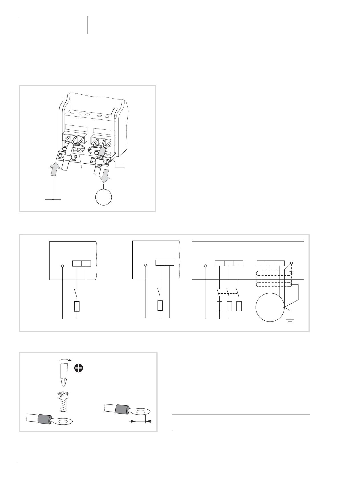
Connection to power section
The following figure shows the general connections for the
frequency inverter in the power section.
Terminal designations in the power section
• L1, L2/N, L3: Connection terminals for the supply voltage (input,
mains voltage):
– Single-phase AC voltage: connection to L2/N and L3 on
MMX11…
– Single phase AC voltage: Connection to L1 and L2/N with
MMX12…
– Three-phase AC voltage: Connection to: L1, L2/, L3 with
MMX32… and MMX34…
• U/T1, V/T2, W/T3: Connection terminals for the three-phase line
to the AC motor (output, frequency inverter).
•
e, PE: connection for protective ground (reference potential).
PES with mounted cable routing plate for shielded cables.
• R+, R-: Connection terminals for external brake resistance (only
with MMX34…, output braking transistor),
The ground connection is connected directly with the cable clamp
plates.
The shielded cables between the frequency inverter and the motor
should be as short as possible. Connect the shielding on both ends
and over a large surface area with protective ground PES
(Protective Earth Shielding). You can connect the shielding of the
motor cable directly to the cable clamp plate (360 degrees
coverage) with the protective ground.
Figure 27: Example: three-phase mains connection
L1 L2/N L3
U/T1
V/T2
W/T3
M
3 ~
3 AC, PE
PES
PE
Figure 28: Connection to power section
e
L3
PE L1 N
L2/N
MMX11...
Input
e
L1
PE L1 N
L2/N
MMX12...
Input
e
L1 L3
PE L1 L2 L3
L2/N
MMX32..., MMX34...
U/T1
W/T3
V/T2
U1
V1
W1
3 ~
e
e
Input Output
Motor
Figure 29: Ground connection
PZ2
M4
1.3 Nm
(0.96 lb-ft)
e
PE
h
The frequency inverter must always be connected to the
ground potential via a grounding cable (PE).
 Loading...


