Appendix
04/10 MN04020001Z-EN
150
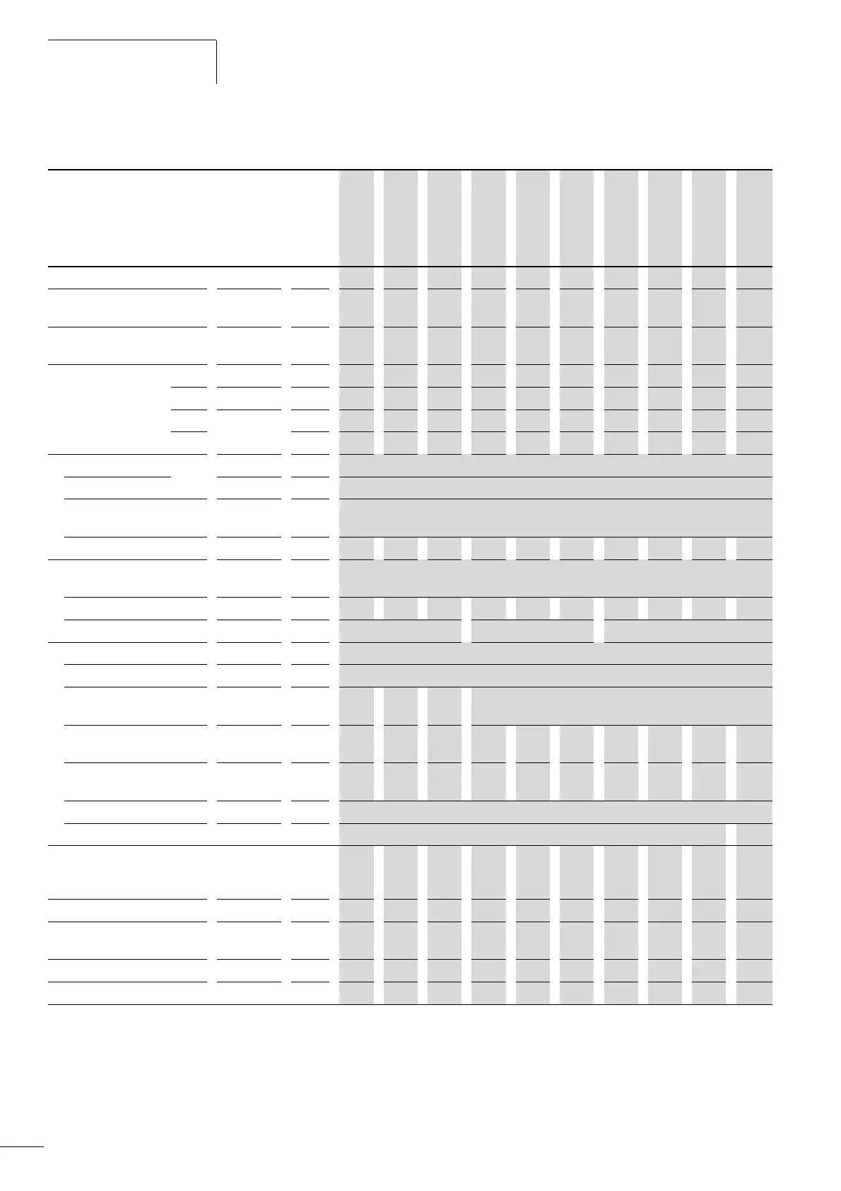
Device series MMX34
MMX34 Symbols
used in
technical
data and
formulae
Unit 1D3 1D9 2D4 3D3 4D3 5D6 7D6 9D0 012 014
1)
Rated operational current (I
e
)I
e
A 1.3 1.9 2.4 3.3 4.3 5.6 7.6 9 12 14
Overload current for 60 s
every 600 s at 50 °C
I
L
A 2 2.9 3.6 5 6.5 8.4 11.4 13.5 18 21
Starting current for 2 s
every 20 s at 50 °C
I
L
A 2.6 3.8 4.8 6.6 8.6 11.2 15.2 18 24 28
Apparent power in
rated operation
400 V S kVA 0.9 1.32 1.66 2.29 2.98 3.88 5.27 6.24 8.32 9.7
480 V S kVA 1.08 1.56 2 2.74 3.57 4.66 6.32 7.48 9.98 11.64
Assigned motor rating 400 V P kWh 0.37 0.55 0.75 1.1 1.5 2.2 3 4 5.5 7.5
2)
460 V HP 1/2 3/4 1 1-1/2 2 3 4
3)
5 7-1/2 10
Power side (Primary side)
Number of phases three-phase
Rated voltage U
LN
V 380 V - 15 % - 480 V + 10 %, 50/60 Hz
(323 - 528 V ±0 %, 45 - 66 Hz ±0 %)
Input current I
LN
A 2.2 2.8 3.2 4 5.6 7.3 9.6 11.5 14.9 18.7
Maximum leakage current to
ground (PE) without motor
MMX34...N... I
PE
mA
MMX34...F... I
PE
mA 45.1 25.1 24.9
Braking torque
Default I/I
e
% F30
Brake-Chopper with external
braking resistance
- - - Max. 100% rated operational current I
e
with external
braking resistance
Minimum
braking resistance
R
B
O - - - 55 55 55 35 35 35 35
Switch-on threshold for the
braking transistor
U
DC
VDC - - - 765 765 765 765 765 765 765
DC braking I/I
e
% F 100, adjustable
Pulse frequency f
PWM
kHz 6 (adjustable 1 – 16) 1 - 4
Heat dissipation at
rated operational
current (I
e
)
P
v
W 21.7 29.7 31.7 51.5 66.4 88.3 116.
9
136.
2
185.
1
223.7
Efficiency h 0.94 0.95 0.95 0.95 0.96 0.96 0.96 0.97 0.97 0.97
Fan (device-internal,
temperature-controlled)
/ / / / / / / / / /
Installation size FS1 FS1 FS1 FS2 FS2 FS2 FS3 FS3 FS3 FS3
Weight m kg
0.55 0.55 0.55 0.7 0.7 0.7 0.99 0.99 0.99 0.99
1) The rated operational data of the MMX34AA014… is limited to 4 kHz at a maximum ambient temperature of +40 °C.
2) Allocated motor output with reduced load torque (about 10 %)
3) Guide value (calculated), no standard rating.
 Loading...


