Parameters
04/10 MN04020001Z-EN
84
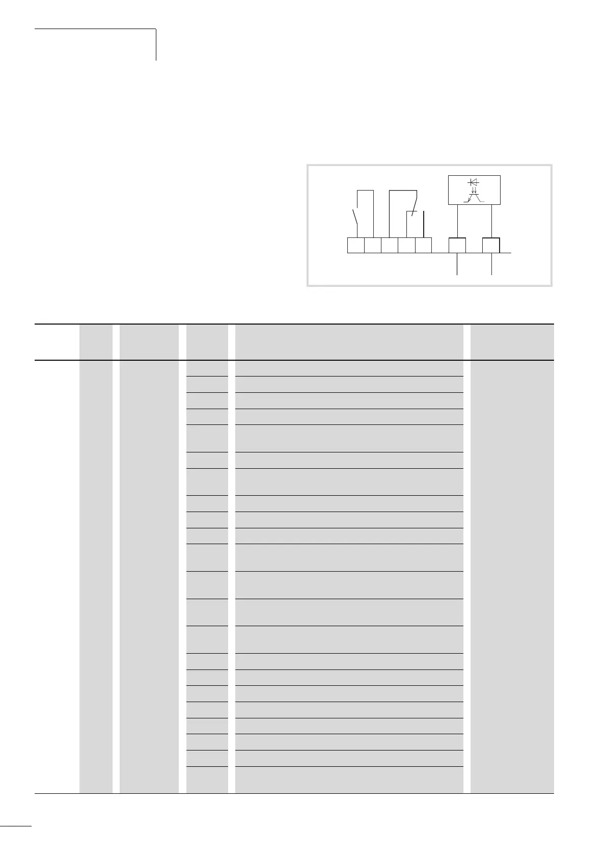
Digital output (P5)
The frequency inverters of the M-Max
TM
series have three digital
outputs in different specifications:
• Relay RO1: N/O contact R13-R14, control signal terminals 22
and 23,
• Relay RO2: changeover contact R21-R22 (N/C contact, control
signal terminals 25 and 24) / R21-R24 (N/O contact, control
signal terminals 25 and 26),
• Transistor output DO: control signal terminal 13 (DO-). Control
signal terminal 20 (DO+) = Input of the supply voltage for the
transistor output.
Notes on electrical connections are found on page 48 and 49.
The messages listed under parameter P5.1 can be assigned
multiple times. These are independent of the selected control level
and operating mode.
Figure 77: Digital outputs
< 50 mA
DO-
DO+
13 20
2322
24 2625
R13
R14
R21
R22
R24
Error
Run
Ready
PNU ID Access right
RUN
Value Description Factory setting
(P1.3)
P5.1 313 / RO1 Signal (Relay 1 Output). 2
0 Deactivated
1 READY, the frequency inverter is ready for operation.
2 RUN, the inverter of the frequency inverter is enabled (FWD, REV).
3 FAULT, error message.
Error detected (= STOP).
4 Error message inverted (no error message).
5 ALARM, warning message
(a section “Protective functions (P8)”.
6 REV (Reverse run), anticlockwise rotating field active.
7 Output frequency = frequency setpoint.
8 Motor controller active.
9 Zero frequency
Output frequency = 0 Hz.
10 Frequency monitoring 1
For the frequency ranges set at P5.4 and P5.5.
11 Frequency monitoring 2
For the frequency ranges set at P5.6 and P5.7.
12 PID monitoring
For the deviation set at P9.17.
13 Overtemperature signal
14 Overcurrent control active.
15 Overvoltage control active.
16 Sequence control active.
17 Sequence control, single step completed.
18 Sequence control, program cycle completed.
19 Sequence control, pause.
20 Counter, value 1 reached. The counter value is f the trigger value
set at P3.21 and can be reset by activating P3.24.
 Loading...


