Parameters
04/10 MN04020001Z-EN
78
Digital input (P3)
The parameter group P3 is used to set the operation and function
of the digital inputs DI1 to DI6.
In the factory setting, the operation of the M-Max
TM
is active via
control signal terminals (I/O) with LOGIC+ (Source type):
• DI1 (control signal terminal 8): FWD (Forward = Start enable
clockwise rotating field).
• DI2 (control signal terminal 9): REV (Reverse = Start enable
anti-clockwise rotating field).
• DI3 (control signal terminal 10): FF1 (fixed frequency
1=10Hz).
• DI4 (control signal terminal 14): FF2 (fixed frequency
2=15Hz).
• DI5 (control signal terminal 15): Reset (acknowledge error
message ALARM).
• DI6 (control signal terminal 16): PID-Off (lock of the PID
controller).
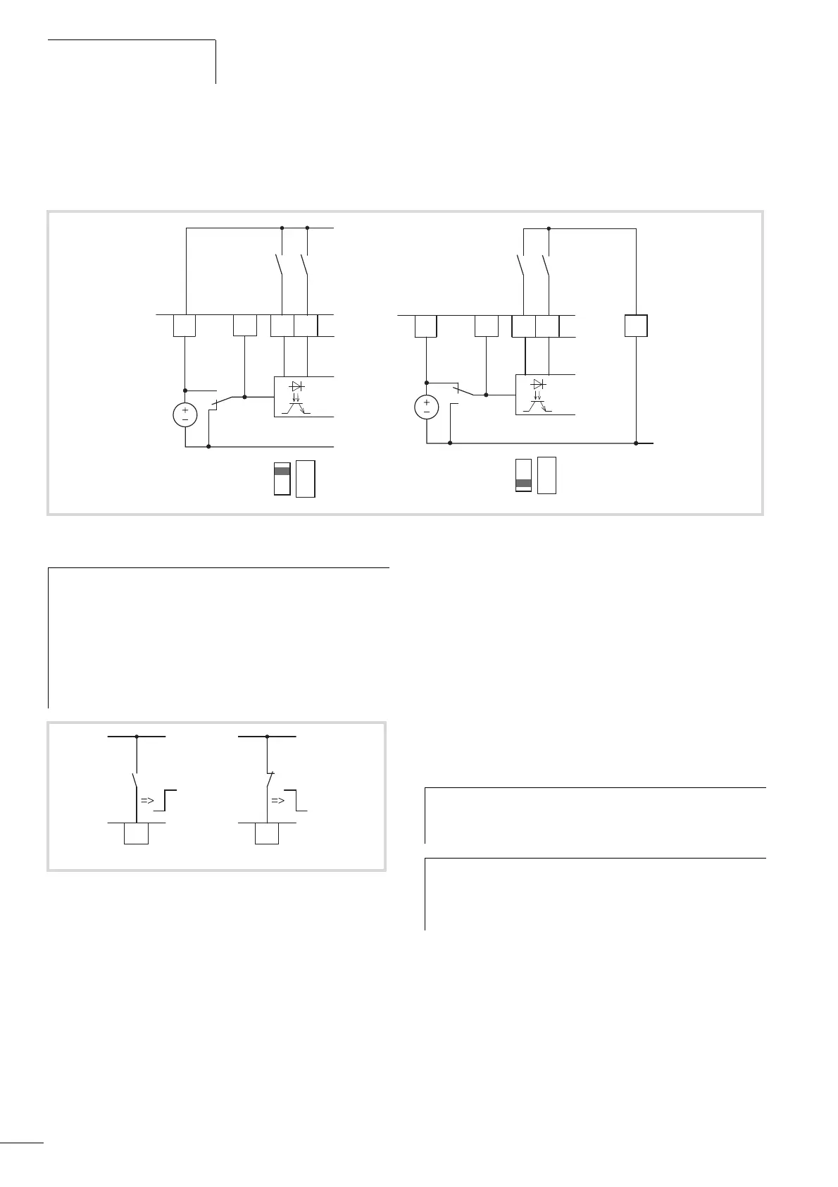
Figure 72: Digital inputs for Source and Sink type
789
DI1
DI2
DI_COM
S1
24 V
6
< 50 mA
+24 V Out
S1 =LOGIC+
(Source type)
LOGIC
- +
789
DI1
DI2
DI_COM
S1
6
< 50 mA
+24 V Out
S1 =LOGIC-
(Sink type)
LOGIC
- +
5
GND
h
Source type (LOGIC+) = switch at the voltage source.
All digital inputs are connected to the voltage sink via
microswitch S1 (0 V = reference potential GND).
Sink type (LOGIC-) = switch at the voltage sink
(0 V = reference potential GND). All digital inputs are
connected to the voltage source via microswitch S1.
Both switch types ensure failsafe actuation.
l
Figure 73: Control logic reaction to a rising or falling edge (Source
type, Sink type)
DI1
8
h
The joint actuation of control signal terminal 10 (FF1) and
control signal terminal 14 (FF2) activates in the factory
setting the fixed frequency FF3 (20 Hz).
h
The individual digital inputs (DI...) can be assigned several
functions. The assigned functions are activated if with
LOGIC+ the control signal terminal is actuated with
+24 V (rising edge, failsafe).
 Loading...


