04/10 MN04020001Z-EN
Parameter menu (PAR)
121
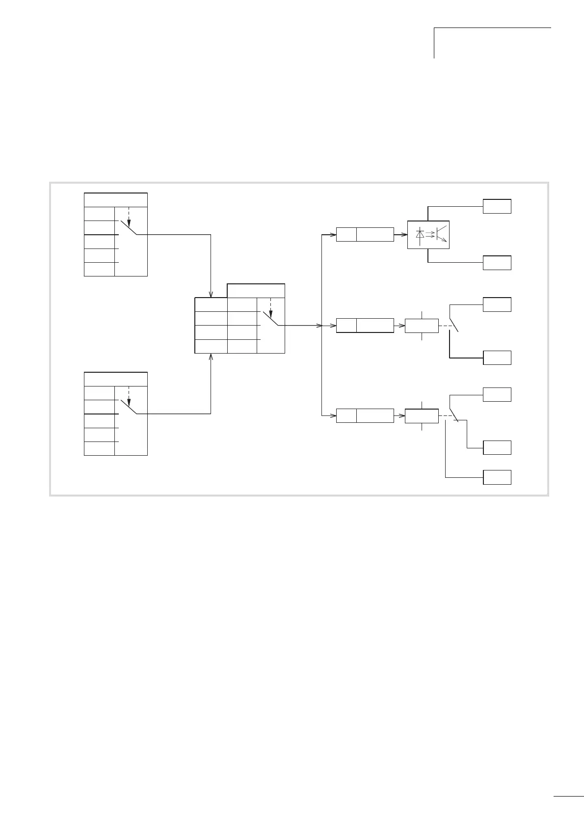
Logic function (P13)
The logic function enables you to link both parameters P13.1 (A)
and P13.2 (B) logically with each other. The result (LOG) can then
be assigned to the digital outputs DO (P5.3), RO1 (P5.1) and RO2
(P5.2). The type of operation (And, Or, Exclusive-Or) is defined in
parameter P13.3.
Example:
Digital output RO1 (N/O contact R13/R14) is required to indicate
during operation that the set current limit has been reached:
• P5.1 = 24, LOG function fulfilled.
• P13.1 = 2, Operation (RUN), signal A
• P13.2 =27, Current monitoring, signal B
• P13.3 = 0, A AND B.
Figure 102: Logic linking of A and B
0
1
...
28
0
1
2
A AND B
A OR B
A XOR B
P13.3
LOG
A
B
P5.324
P5.224
25
24
26
P5.124
22
RO1
RO2
DO1
23
R14
R21
R22
R24
R13
20
DO+
13
DO-
P13.1
0
1
...
28
P13.2
 Loading...


