Appendix
04/10 MN04020001Z-EN
148
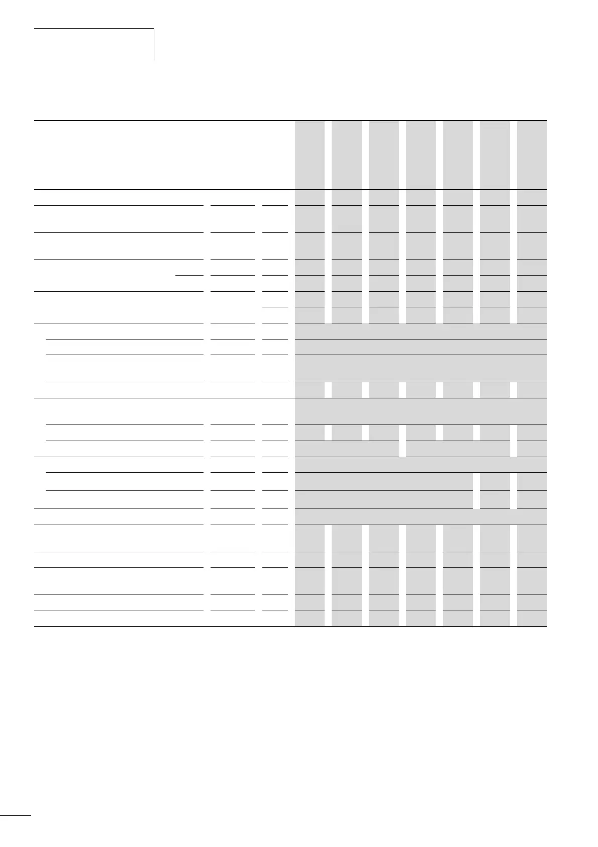
Device series MMX12
MMX12 Symbols
used in
technical
data and
formulae
Unit 1D7 2D4 2D8 3D7 4D8 7D0 9D6
Rated operational current I
e
A 1.7 2.4 2.8 3.7 4.8 7 9.6
Overload current for 60 s every 600 s
at 50 °C
I
L
A 2.6 3.6 4.2 5.6 7.2 10.4 14.4
Starting current for 2 s every 20 s
at 50 °C
I
L
A 3.4 4.8 5.6 7.4 9.6 14 19.2
Apparent power at rated operation 230 V S kVA 0.68 0.96 1.12 1.47 1.91 2.79 3.82
240 V S kVA 0.71 0.99 1.16 1.54 1.99 2.91 3.99
Assigned motor rating 230 V P kWh 0.25 0.37 0.55 0.75 1.1 1.5 2.2
HP 1/3
1)
1/2 1/2 3/4 1 2 3
Power side (primary side):
Number of phases single-phase or two-phase
Rated voltage
U
LN
V 208 V - 15 % - 240 V + 10 %, 50/60 Hz
(177 - 264 V ±0 %, 45 - 66 Hz ±0 %)
Input current I
LN
A 4.2 5.7 6.6 8.3 11.2 14.1 15.8
Maximum leakage current to ground (PE)
without motor
MMX12...N... I
PE
mA
MMX12...F... I
PE
mA 15.4 11.8 24.4
Braking torque
Default M/M
N
% F 30
DC braking I/I
e
% F 100, adjustable
Pulse frequency f
PWM
kHz 6 (adjustable 1 – 16)
Heat dissipation at
rated operational current (I
e
)
P
v
W 17.9 24.6 29.2 40.2 49.6 66.8 78.1
Efficiency h 0.93 0.93 0.95 0.95 0.95 0.96 0.96
Fan (device-internal,
temperature-controlled)
/ /
/ / / / /
Installation size FS1 FS1 FS1 FS2 FS2 FS2 FS3
Weight m kg
0.55 0.55 0.55 0.7 0.7 0.7 0.99
1) Guide value (calculated), no standard rating
 Loading...


