Parameters
04/10 MN04020001Z-EN
88
Drives control (P6)
In this parameter group (P6), you can define the operating
conditions for the frequency inverter M-Max
TM
.
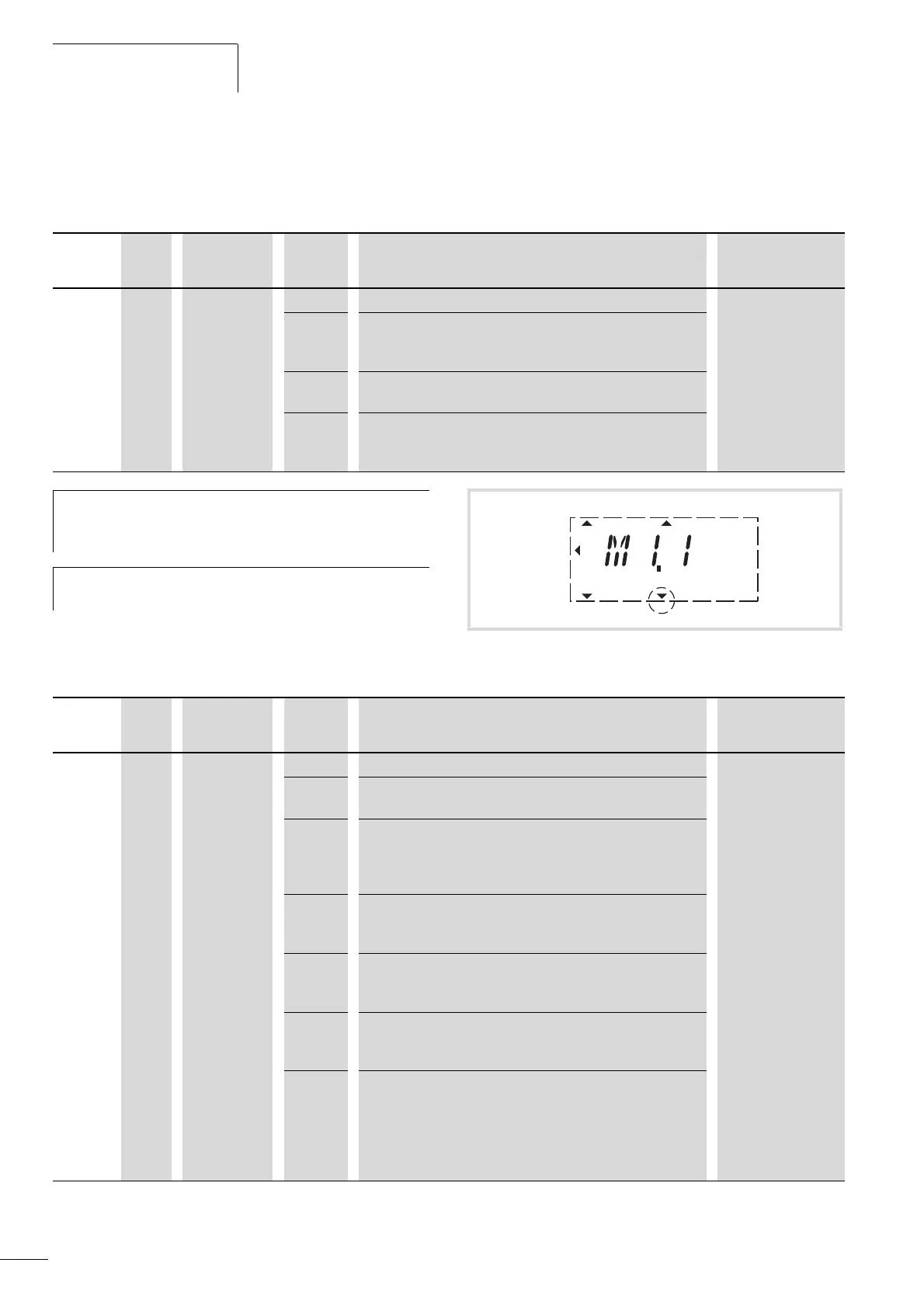
The control level selected with parameter P6.1 or with the LOC/
REM button is shown on the bottom page in the LCD display (see
figure 79).
PNU ID Access right
RUN
Value Description Factory setting
(P1.3)
P6.1 125 / Control place 1 1
1 Control signal terminals (I/O)
You can switch directly between I/O and KEYPAD with the LOC/
REM button.
2 Control unit (KEYPAD)
The LOC/REM button has no function here.
3 Fieldbus (BUS)
You can switch directly between BUS and KEYPAD with the LOC/
REM button.
h
Selecting the control levels can be done directly with the
LOC/REM button between the control levels selected in
P6.1 and the operating unit.
h
During operation (RUN) the drive is always stopped
(STOP) when changing control levels (LOC/REM button).
Figure 79: Example: Control level I/O activated
RUN STOP ALARM FAULTREADY
REF
FWD REV I/O KEYPAD BUS
MON
PAR
FLT
PNU ID Access right
RUN
Value Description Factory setting
(P1.3)
P6.2 117 / Setpoint Source 3
0 Fixed frequency (FF0)
The value can be set in parameter P10.1.
1 Control unit (KEYPAD)
This setting causes the setpoint defined at REF to be read. It can
be set via the keypad with the arrow buttons or at parameter
P6.15.
2 Fieldbus (BUS)
Setpoint entry via Modbus RTU (control signal terminals A and B)
or optional fieldbus connection (e.g. CANopen, PROFIBUS DP).
3 AI1 (analog setpoint 1)
Voltage set value: 0 (2) – +10 V at control signal terminal 2.
Scaling and filtering: P2.1 to P2.4 .
4 AI2 (analog setpoint 2)
Current setpoint value: 0 (4) -20 mA to control signal terminal 4
Scaling and filtering: P2.5 to P2.8.
5 Motor potentiometer
The actuation is implemented via the digital inputs assigned at
P3.18 and P3.19 (DI1 - DI6). The required acceleration and
deceleration times can be set at P6.5 (acc1) and P6.6 (dec1).
Assigning a digital input (DI1 - DI6) at P6.20 enables the set value
of the motor potentiometer to be set directly to zero.
 Loading...


