Installation
04/10 MN04020001Z-EN
36
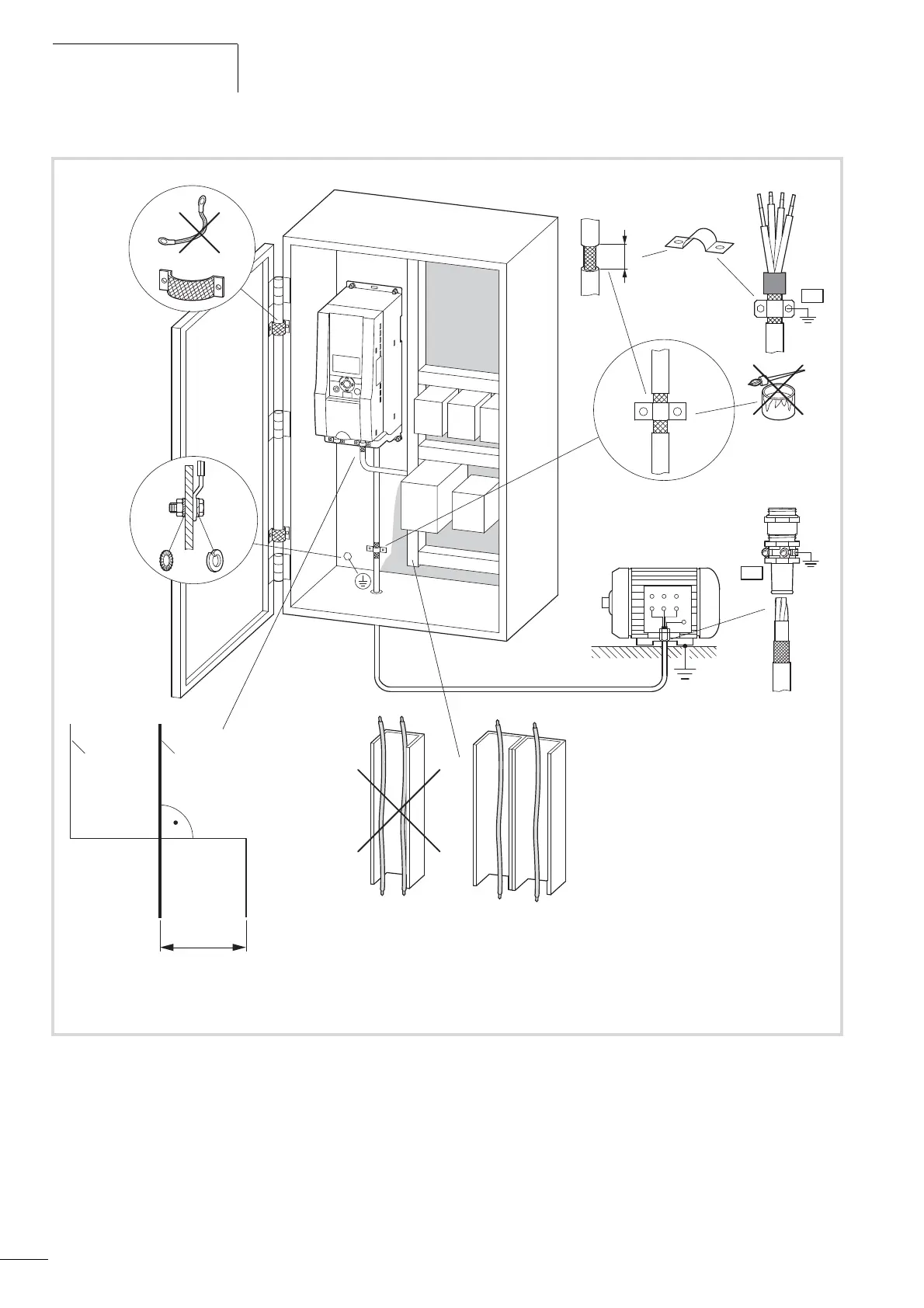
Figure 26: EMC-compliant setup (example: M-Max
TM
)
a Power cable: L1, L2/N, L3 and U/T1, V/T2, W/T3, R+, R-
b Control and signal lines: 1 to 26, A, B, fieldbus connection
Large-area connection of all metallic control panel components.
Mounting surfaces of frequency inverter and cable shielding must be free from paint.
Connect the cable shielding in the output of the frequency inverter with a large surface area contact to the ground potential (PES).
Large-area cable shield contacts with motor.
Large-area earth connection of all metallic parts.
PE
PES
W2
U2
V2
U1
V1
W1
PE
ba
a L1, L2, L3, N, U, V, W, R+, R-
b 1, 2, … 26, A, B
f
300 mm
f 11.81 “
115/120 V AC
230/240 V AC
400 V AC
460/480 V AC
24 V DC
115/120 V AC
230/240 V AC
400 V AC
460/480 V AC
24 V DC
PES
15
0.59 “
I
OK
BACK
RESET
LOC
REM
 Loading...


