Effective April 2010
8 Eaton Corporation www.eaton.com
Eaton SPD Series
Surge Protective Device for Integrated Units
Instruction Manual IM01005019E - Rev. 3
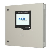
3.3 Remote Display Panel (RDP) Option
The Eaton Series SPD displays may be monitored on a remote
display panel (RDP). This is indicated by the catalog style with a
'B' suffix (such as SPD250480D2B).
A separately purchased RDP cable is required to connect the
SPD unit to the display.
Table 2 lists these cables and their part numbers.
Table 2. RDP Cable Options
Description
Catalog No.
4 ft. Cable for RDP
8 ft. Cable for RDP
12 ft. Cable for RDP
SPDRDCAB04
SPDRDCAB08
SPDRDCAB12
4.0 Troubleshooting
Many SPD failures result from improper installation. Once the
SPD is installed properly, it is a highly reliable unit.
If the SPD does not function properly, first confirm that it is
installed properly. See Section 2, “Installation.”
If the SPD malfunctions after it has been operating routinely,
refer to Table 3. This Troubleshooting Chart identifies possible
causes and solutions to the malfunction. Further assistance
may be obtained by calling Eaton’s Applications Engineers, at
1-800-809-2772, option 4, sub-option 2, including being directed
to the warranty process if applicable.
3.2.4 SPD Display Rotation
The SPD display can be rotated on the SPD enclosure, up to 360
degrees. This allows you to position the display for the best vis-
ibility regardless of the position in which the SPD is installed.
Rotations are at 90, 180, and 270 degrees.
For a typical horizontal mounting see Figure 21. For a typical ver-
tical mounting see Figure 22.
Reposition the SPD display as follows:
1. Remove power from the unit.
2. Remove and discard the perforated overlay material at the
two opposite corners of the display.
3. Remove the two phillips head screws that hold the display.
4. Rotate the display to the desired position. Be careful not to
overstress the display ribbon cable.
5. Place the display back onto the SPD enclosure. Again, be
careful not to overstress or crimp the ribbon cable.
6. Replace the two phillips head screws. Tighten screws to
1.35 Nm (12 in-lbs).
7. Restore power to the unit.
Figure 21. Typical Horizontal Display Mounting
Figure 22. Typical Vertical Display Mounting

 Loading...


