KS 3-2010
Page 20
7.4 Auxiliary Switch Tests
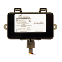
Figure 9
Sample Auxiliary Switch
7.4.1 Purpose
To verify that the contacts of the auxiliary switch(es) (see Figure 9) change status when the main switch
contacts are opened and closed.
7.4.2 Equipment
This test requires an ohmmeter or low voltage continuity tester.
7.4.3 Procedure
WARNING—Follow all safety procedures described in Section 2.
7.4.3.1 Remove the control circuit wires from the terminals (or leads) of the auxiliary switch(es).
7.4.3.2 Starting with the main switch in the OFF position, use an ohmmeter or continuity tester
connected to the terminals (or leads) of each auxiliary switch, to verify that its contact position
(open or closed) is in agreement with the wiring diagram provided by the manufacturer.
7.4.3.3 Connect the ohmmeter or low voltage continuity tester to the terminals (or leads) of one
auxiliary switch to monitor the contact.
7.4.3.4 Operate the main switch to the ON position. The auxiliary switch contact should change
position.
7.4.3.5 Repeat steps 7.4.3.2 through 7.4.3.4 for each auxiliary switch.
© Copyright 2010 by the National Electrical Manufacturers Association.

 Loading...


