Installation
S811+ Soft Starter MN03900001E—November 2012 19
Network Control Terminal Block
The network control terminal block provides connections D0,
D1, and Ground for connection directly to a ModBus system.
Additional networks may be accommodated by utilizing
communications adapters.
Typical Control Wiring Diagrams
Each diagram illustrates a typical wiring scheme for the
options described. The additional components shown on the
diagrams are not included, but may be purchased from
Eaton.
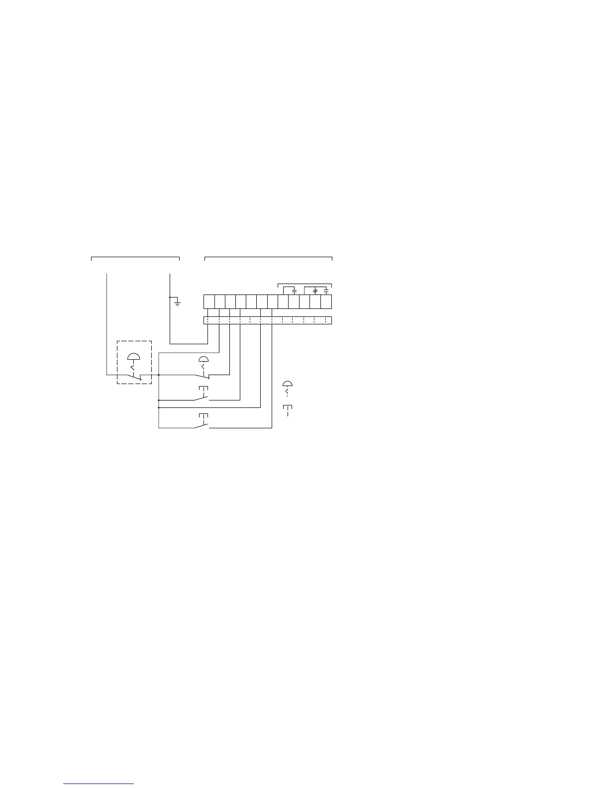
Basic Connection Diagram for 3-Wire Pushbutton
Notes
1. A minimum wire of 14 AWG (2.5 mm
2
) should be used
between the 24 Vdc control power supply and the
control terminal block.
2. See Using an Auxiliary Relay section below if it is desired
to use a relay instead of an indicating lamp for terminals
13, 14, 95, 96 and 98.
3. 120 Vac may be applied to terminals 13, 14, 95, 96,
and 98.
4. Add ferrite, Fair-Rite #0446176451 to DC Power Leads
and Control I/O Leads (all through one ferrite) at S811+.
5. Functionality of terminals 1, 2, 3, and 4 are shown in the
default configuration. These terminals are programmable
for other functions. In a 3-wire control system, at least
one terminal must be assigned to a Start command
(RUN1) signal.
6. Auxiliary relays: 3 amps at 120 Vac or 24 Vdc, 10 amps
max. (resistive) switching.

 Loading...