Appendix H—Universal Communications Adapter
S811+ Soft Starter MN03900001E—November 2012 75
Appendix H—Universal Communications Adapter
External adapters can be connected to the S811+ to enable the unit to be controlled
by networks other than Modbus.
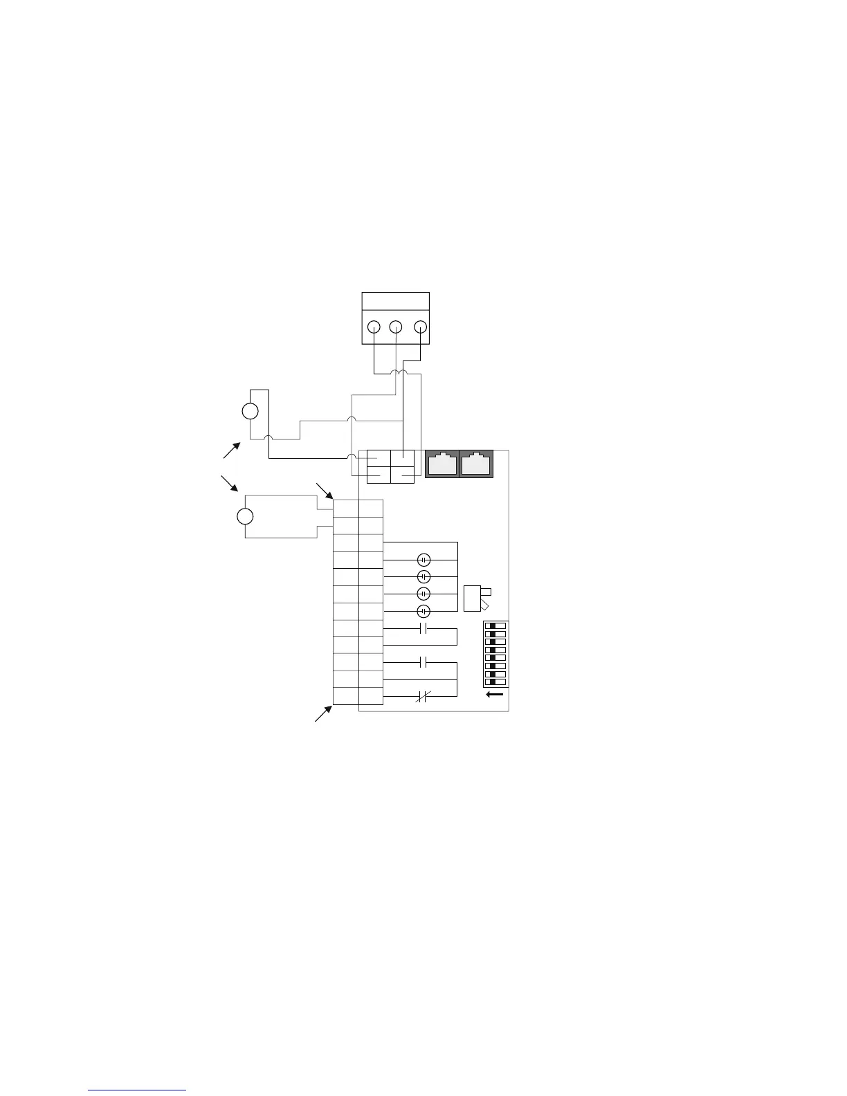
Connect the adapter in accordance with the wiring diagram below.
Wiring Diagram
Notes
1. Connect the C441 RS485 Modbus Port on the Universal Communications Adapter to
the S811+ CH0 Net terminal block.
2. Connect 24 Vdc to either the RS485 port or the 12 position I/O terminal as shown.
Only one (1) connection is required.
3. Set the S811+ communications port for Modbus by setting dip switch S2 (on).
4. Use the S811+ address dip switches to set the S811+ Modbus address to 1.
5. Dip switch S2 is used for level/edge sense, and has no effect on the Communications
adapter.

 Loading...