Installation
20 S811+ Soft Starter MN03900001E—November 2012
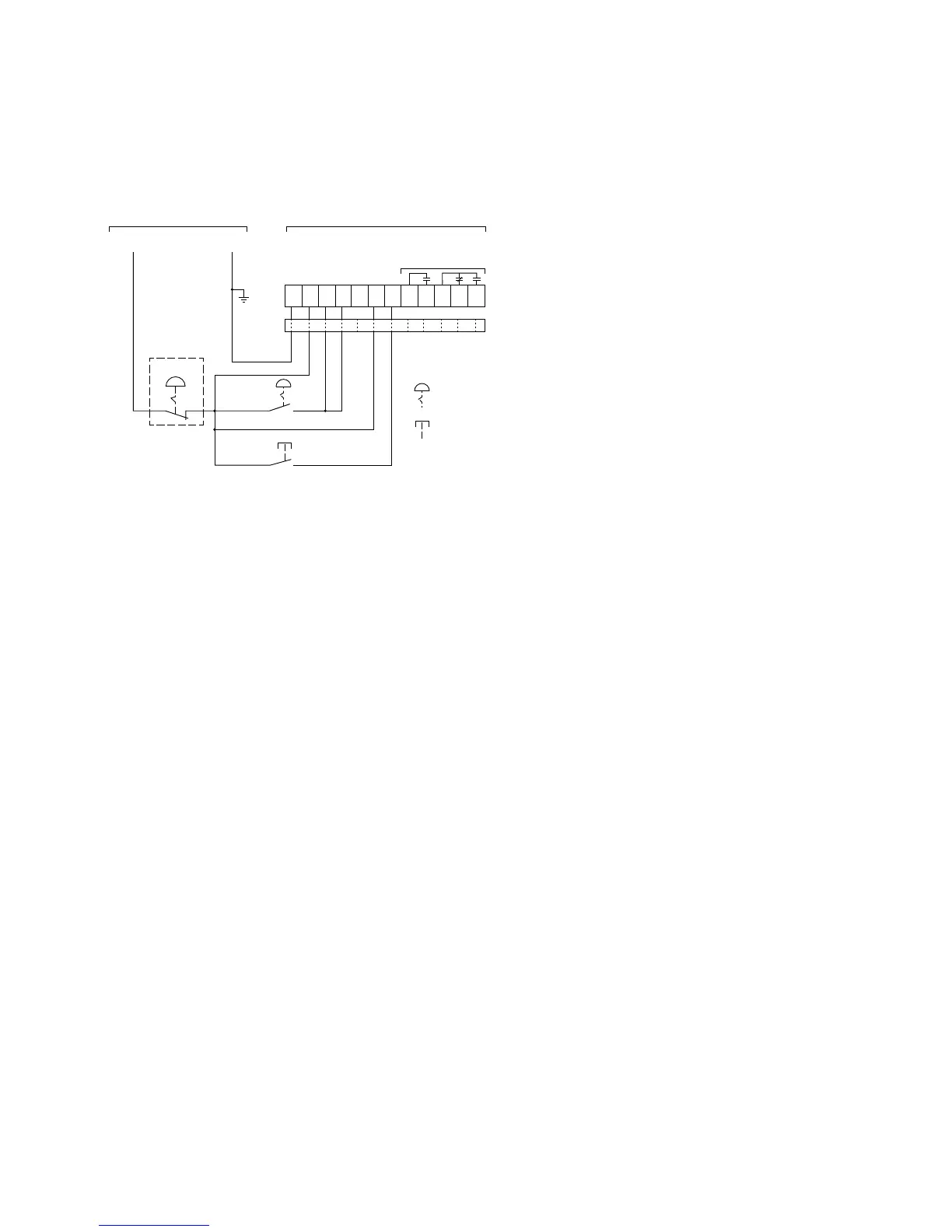
Basic Connection Diagram for 2-Wire Pushbutton
Notes
1. A minimum wire of 14 AWG (2.5 mm
2
) should be used
between the control power supply and the control
terminal block.
2. See Using an Auxiliary Relay section below if it is desired
to use a relay instead of an indicating lamp for terminals
13, 14, 95, 96 and 98.
3. 120 Vac may be applied to terminals 13, 14, 95, 96,
and 98.
4. Add ferrite, Fair-Rite #0446176451 to DC Power Leads
and Control I/O Leads (all through one ferrite) at S811+.
5. Functionality of terminals 1, 2, 3, and 4 are shown in the
default configuration. These terminals are programmable
for other functions. In a 2-wire control system, at least
one terminal must be assigned to a Start command
(RUN1) signal.
6. Auxiliary relays: 3 amps at 120 Vac or 24 Vdc, 10 amps
max. (resistive) switching.

 Loading...