Functional Description
S811+ Soft Starter MN03900001E—November 2012 27
Control Functions
Network Control
When the S811+ is in Network control and a 24 Vdc signal is
present at control block terminal “P”, it is ready to respond
to motor START control commands issued through the
Network Comms Port.
The Local Control must be disabled to allow Network control.
Local Control is available for configuration through a
programmable function on the control terminal block
(default—terminal #3) or enabling the Local Ctrl Only
parameter in the Advanced I/O Menu.
The Comms Port enables complete communications
between the S811+ and the Network including changing
parameters settings, issuing control commands, and
monitoring selected operational values via ModBus, or other
networks. The Comms Port provides ModBus motor control
commands as the native protocol.
Local Control
S811+ Local Control (default) consists of Permissive, Start,
Jog, Local and Reset 24 Vdc control commands to the
Terminal Block. The S811+ can also be started/stopped from
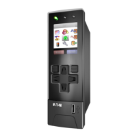
the Digital Interface Module.
The default configuration of the Control Terminal Block
utilizes five (5) functions to control the S811+ soft starter.
Terminals 1 thru 4 may be (re)programmed for other
functions.
Terminal P–Permissive (run enable)—Must be energized
with 24 Vdc to enable operation of the S811+ soft starters by
either local and/or network control. If power is lost or
removed from Permissive terminal at any time, the unit will
initiate a coast Stop, Soft Stop, or Pump Stop in accordance
with the setup parameter selections. If the S811+ is being
controlled from a network, loss of the Permissive signal will
initiate a coast Stop, Soft Stop, or Pump Stop in accordance
with the setup parameter selections. Functionality of this
terminal cannot be changed.
Terminal 1—Start (default)—If 24 Vdc is present at the
Permissive terminal, momentary application of 24 Vdc to the
Start terminal will initiate a Voltage Ramp or Current Limit
start for the S811+ soft starter. Application of 24 Vdc may be
maintained
Note: With level sensing control, if 24 Vdc is lost or removed
from the Permissive terminal at any time, the unit will
initiate a stop in accordance with setup parameter
selections. A restart may occur when 24 Vdc is
restored or reapplied if:
a) 24 Vdc is present on the Start terminal
(maintained), and;
b) the S811+ shows a Ready LED (not faulted) status.
If the starter has faulted and the fault condition
clears AND the Auto Reset Mode parameter in the
Operation Mode list is set to AUTO, the starter will
restart.
See the Edge and Level Sensing sections on Page 28
for additional details.
If the AUTO Reset Mode setting is used with level
sensing, CAUTION must be exercised to assure
that any restart occurs in a safe manner. Motor
restart may occur immediately and unexpectedly
after any fault condition has cleared.
Terminal 2—Jog (default)—Application of 24 Vdc power to
the Jog terminal will apply a Start command for as long as
the signal is present. The S811+ will perform a Start ramp in
accordance with Start parameters. If the motor achieves
synchronous speed, the internal bypass contactors will not
close. When the 24 Vdc signal is removed, the soft starter
will perform a coast stop, irrespective of any Soft Stop or
Pump Stop parameter values.
Terminal 3—Local (default)—Application of 24 Vdc power to
the L
ocal terminal will allow Start or Jog control from the
terminal block.
Note: Local Control only may be enabled by the Local Ctrl
Only parameter in the Advanced I/O menu. If this
parameter is enabled, control commands from any
network will not be recognized.
Terminal 4—Reset (default)—Application of 24 Vdc power to
the Reset terminal will reset the soft starter after all fault
conditions are cleared and no active fault is present. If the
Fault LED is not able to be reset, a fault condition still exists
and must be corrected. A Reset signal may also be sent from
any network connection.

 Loading...


