June 2006
6
For more information visit: www.EatonElectrical.com CA04000006E
SVX9000 Adjustable Frequency Drives
Open Drives
Catalog Number Selection
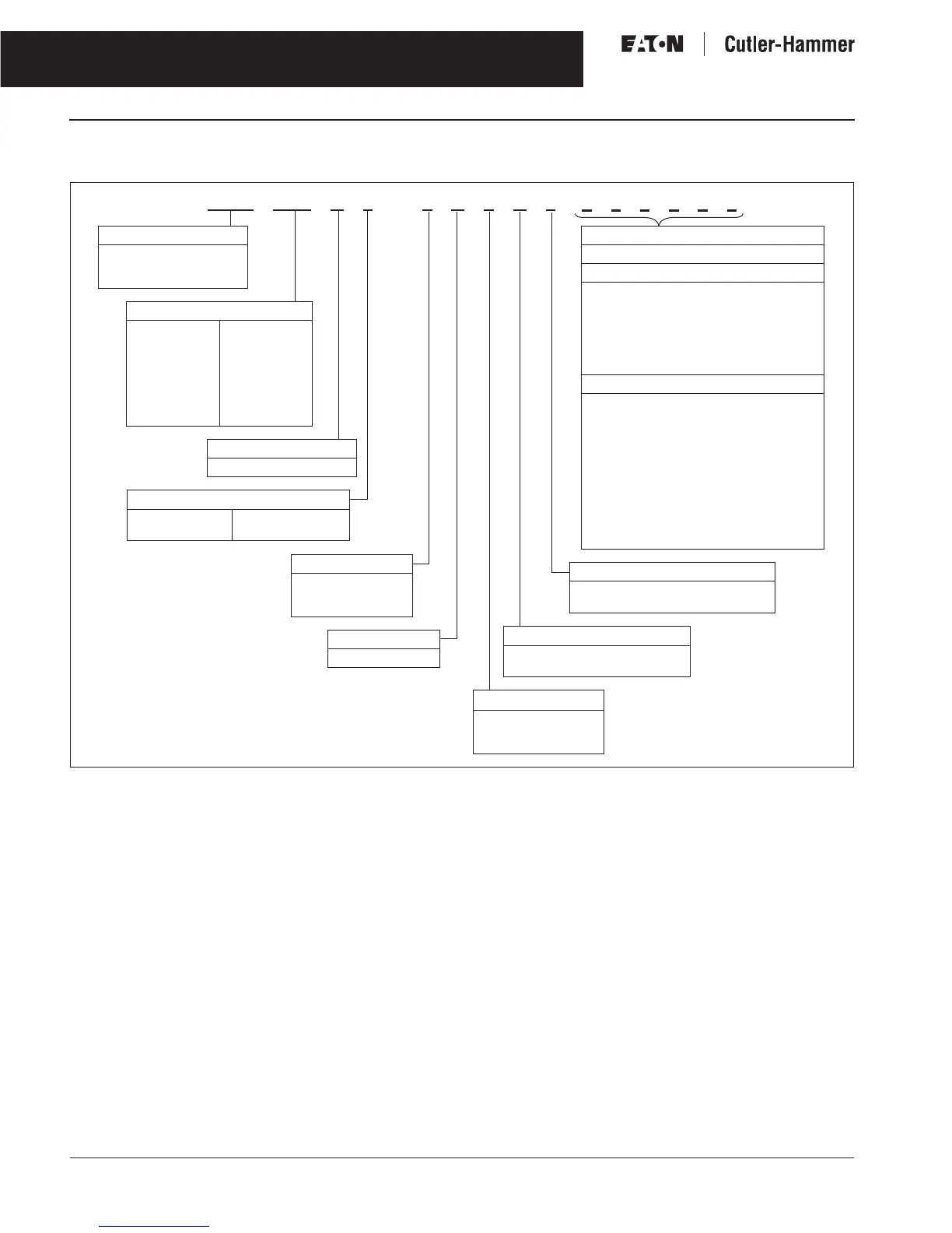
Table 4. Adjustable Frequency Drive Catalog Numbering System
All 230V Drives and 480V Drives up to 200 hp (I
H
) are only available with Input Option 1 (EMC Level H). 480V Drives 250 hp (I
H
) or larger are available
with Input Option 2 (EMC Level N). 480V Drives are available with Input Option 4 (EMC Level L). 575V Drives 200 hp (I
H
) or larger are only available
with Input Option 2. 575V Drives up to 150 hp (I
H
) are only available with Input Option 4 (EMC Level L).
480V Drives up to 30 hp (I
H
) are only available with Brake Chopper Option B. 480V Drives 40 hp (I
H
) or larger come standard with Brake Chopper
Option N. 230V Drives up to 15 hp (I
H
) are only available with Brake Chopper Option B. 230V Drives 20 hp or larger come standard with Brake Chopper
Option N. All 575V Drives come standard without Brake Chopper Option (N). Note: N = No Brake Chopper.
480V Drives 250 hp (I
H
) and larger are available with enclosure style 0 (Chassis); 690V Drives 200 hp (I
H
) and larger are available with enclosure
style 0 (Chassis).
480V and 690V FR10 Freestanding Drives are available with enclosure style 1 (NEMA Type 1) and enclosure style 2 (NEMA Type 12). FR11 Freestanding
Drives only available with enclosure style 1 (NEMA Type 1).
Factory promise delivery. Consult Sales Office for availability.
Keypad
A = Alphanumeric
S V X 0 1 0 A 1 –4A 1 B 1
Board Modifications
1 = Standard Boards
2 = Conformal (Varnished) Coating
Brake Chopper Options
N = No Brake Chopper Circuit
B = Internal Brake Chopper Circuit
Input Options
1 = 3-phase, EMC H
2 = 3-phase, EMC N
4 = 3-phase, EMC L
Options
Options appear in alphabetical order.
Extended I/O Card Options
B1 = 6 DI, 1 ext +24V DC/EXT +24V DC
B2 = 1 RO (NC/NO), 1 RO (NO), 1 Therm
B4 = 1 AI (mA isolated), 2 AO (mA isolated),
1 ext +24V DC/EXT + 24V DC
B5 = 3 RO (NO)
B8 = 1 ext +24V DC/EXT +24V DC, 3 Pt100
B9 = 1 RO (NO), 5 DI 42 – 240V AC Input
Communication Cards
CA = Johnson Controls N2
CI = Modbus TCP
CJ = BACnet
CK = Ethernet IP
C2 = Modbus
C3 = Profibus DP
C4 = LonWorks
C5 = Profibus DP (D9 Connector)
C6 = CanOpen (Slave)
C7 = DeviceNet
C8 = Modbus (D9 Type Connector)
D3 = RS-232 with D9 Connection
Product Family
SVX = Open Drives
SPX = Open Drives
FR10 & greater
Horsepower Rating
F07 = 3/4 hp
F15 = 1-1/2 hp
007 = 7-1/2 hp
010 = 10 hp
050 = 50 hp
125 = 125 hp
350 = 350 hp
700 = 700 hp
800 = 800 hp
900 = 900 hp
H10 = 1000 hp
H12 = 1200 hp
H13 = 1350 hp
H15 = 1500 hp
H16 = 1600 hp
H20 = 2000 hp
AFD Software Series
A = Standard Software
Enclosure
0 = Chassis
1 = NEMA Type 1
2 = NEMA Type 12
Voltage Rating
2 = 230 (208 – 240) V
4 = 480 (380 – 500) V
5 = 575 (525 – 690) V

 Loading...


