HANDLE AND CONTROL SYSTEM
CS-2510TES
250Ts, 250TCs
69
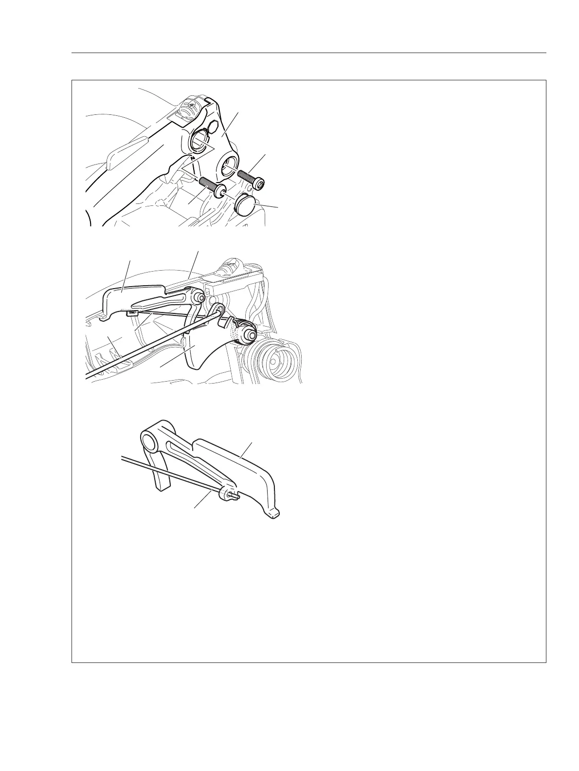
9-1 Replacing throttle control parts
{Disassembling}
1. Remove starter assembly, sprocket guard, chain
catcher, sprocket guard plate, brake lever. (Refer
to “6-1 Replacing brake lever and torsion spring“)
2. Remove plug (A) and bolt (B).
NOTE :
If throttle rod prohibits removing bolt (B),
pull throttle trigger downward to move throttle rod.
3. Remove bolt (C) and rear handle lid (D).
4. Remove throttle trigger (E) with throttle rod (F),
torsion spring (G), and throttle lockout (H) from
rear handle (J).
5. Remove air cleaner cover, air fi lter, and carbure-
tor elbow (Refer to “4-1 Inspecting air fi lter” ).
6. Disconnect throttle rod (F) from carburetor.
7. Check throttle control parts and replace defec-
tive part(s) with new one as required.
{Assembling}
8. Insert throttle rod (F) to rear handle (J) and con-
nect throttle rod (F) to carburetor (Refer to “4-14
Installing carburetor”).
9. Insert throttle rod (F) to hole of throttle triger (E).
10. Assemble throttle trigger (E) together with tor-
sion spring (G) on rear handle (J).
11. Insert torsion spring end (g) to hole of throttle
lockout (H) as shown.
12. Assemble throttle lockout (H) with torsion
spring (G) on rear handle (J).
13. Assemble rear handle lid (D) (Refer to sec-
tion 23 and 24 of “9-3 Replacing rear handle and
springs”) and tighten bolt (B) and (C). Install plug (A)
on rear handle lid (D).
NOTE :
If throttle rod prohibits installing bolt (B),
pull throttle trigger downward to move throttle rod.
14. Assemble removed parts.
STOP
STOP
B
A
C
D
E
F
G
H
J
H
g