GUIDE BAR MOUNTING SYSTEM
CS-2510TES
250Ts, 250TCs
75
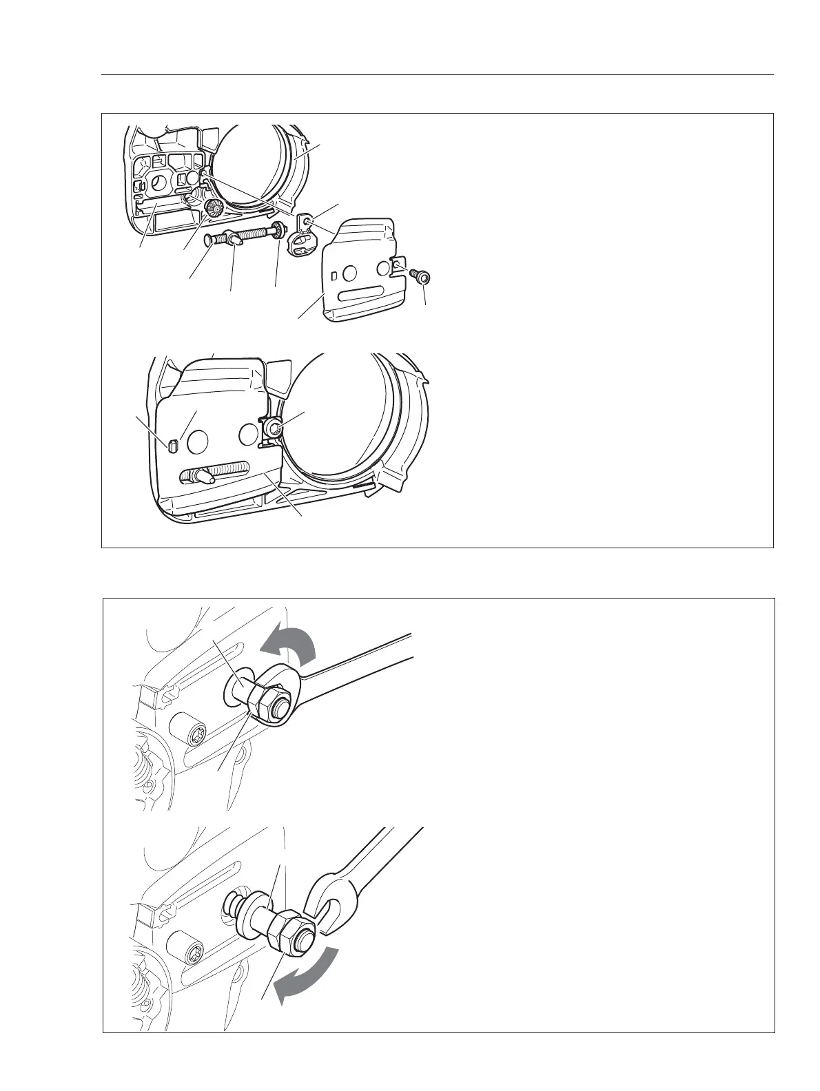
10-2 Replacing chain tensioner
{Disassembling}
1. Remove bolt (A), sprocket guard plate (B), cover
(C), tensioner screw (D), chain tensioner (E), bevel
gear (F) and (G) from sprocket guard (H).
2. Check removed parts for damage or wear. Re-
place with new part(s) as required.
{Assembling}
3. Install bevel gear (G) into sprocket guard (H).
4. Screw chain tensioner (E) on tensioner screw (D).
5. Put bevel gear (F) on tensioner screw (D).
6. Install sub assembled tensioner screw in slot (h1)
of sprocket guard (H) confirming engagement of
bevel gear (F) and (G).
7. Reassemble cover (C) and sprocket guard plate
(B). Tighten bolt (A).
NOTE
: Make sure to hook tub (h2) on sprocket
gurad to hole (b) of sprocket guard plate (B)
A
B
C
D
E
F
G
H
h1
A
B
h2
b
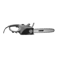
10-3 Replacing guide bar stud
{Disassembling}
1. Remove chain catcher and sprocket guard plate
from engine cover.
2. Install two nuts on defective stud (A) and tighten
them against each other.
3. Turn nut (B) counterclockwise to remove stud.
NOTE:
If it is hard to remove or broken stud is too
short for tightening two nuts, hold defective stud
by vise and turn the chain saw body counterclock-
wise, or use a suitable stud remover.
{Assembling}
4. Install two nuts on new stud and tighten them
against each other.
NOTE:
Apply a small amount of thread locking
sealant in the thread hole (locktite #272 or equiva-
lent).
5. Turn nut (C) clockwise to install stud.
6. Reassemble removed parts.
B
A
C
A