AS9216 Installation and
Maintenance Manual
Platform Installation
492006-2306-013-A00 ECI Telecom Ltd. Proprietary 3-7
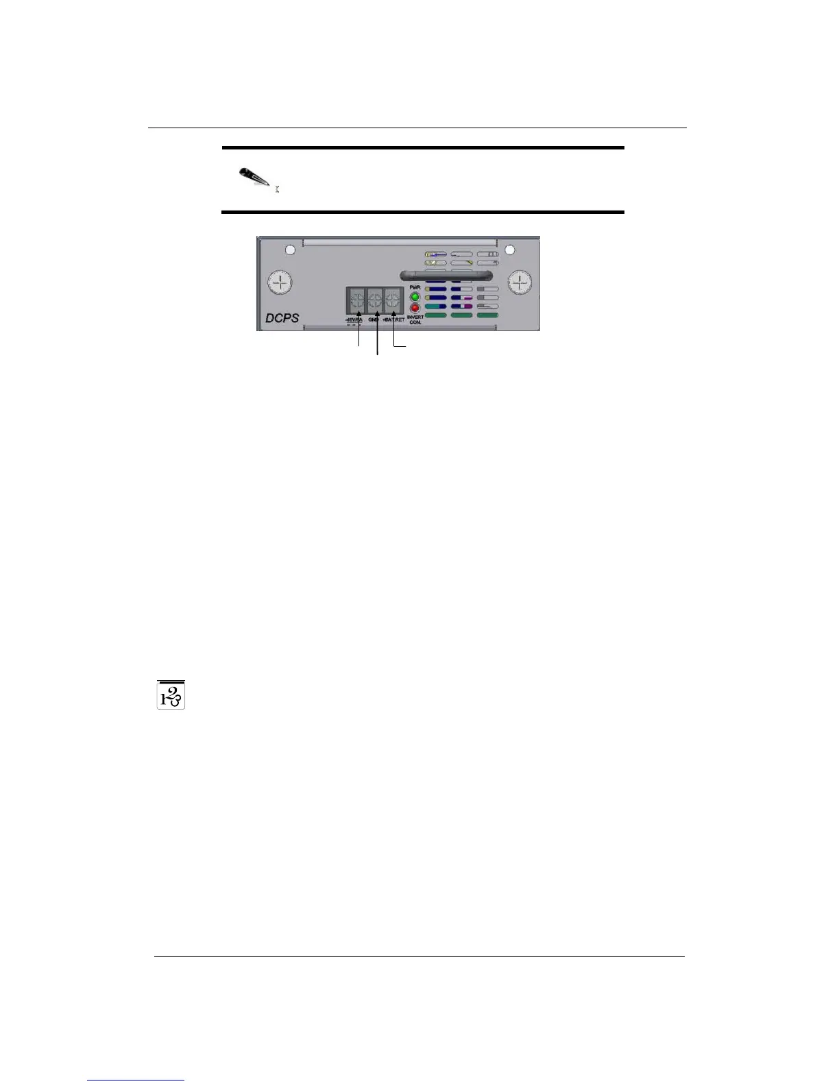
NOTE: Neither the +BAT.RET nor the -48VDC are
connected to the GND terminal. If required, this can be
performed externally by the user.
Figure 3-5: The AS9216 9216-DCPS
2. Color-code the wiring according to local standards to ensure that the input
power and ground lines are easily distinguished.
3. Turn on the power to the feed lines at the supply circuit-breaker.
4. Verify that the 9216-DCPS ' PWR LED and the relevant PS LED are green.
5. If you have a redundant 9216-DCPS, repeat the steps above to connect it.
In such scenario, both modules' PS LEDs are turned on.
Connecting to the Console Port
The AS9216 console port is a EIA232 VT-100 compatible port through which
you can define the device's basic operational parameters.
To connect the device to your PC using the Console Port:
1. Connect the RJ-45 connector of the console cable to the device's Console
Port (CON).
2. Connect the other side of the cable to your PC.
3. Configure the PC port to 9600-N-8-1 or:
9600 bps
no parity
8 data bits
1 stop bit
no flow control