4. Mount the gauge tube in verc
al direcon to minimise the build up of process
parculates and condensable vapours within the gauge.
5. For precision, we recommend that the atmosphere and vacuum adjustment must
be done before use. Refer to Maintenance on page 36.
4.3 Connect the gauge
4.3.1 Connect to the vacuum system
To connect the gauge to the vacuum system:
▪ Use an O-ring or a centring-ring or a co-seal to connect the gauge with NW16 or
NW25 ange to a similar ange on the vacuum system. The gauge is not
compable with centering ring adaptors.
▪ Use a new copper gasket to connect the gauge with a DN16CF ange and a new
face seal metal gasket to connect the gauge with a 8VCR or 4VCR ange to a similar
ange on the vacuum system.
▪ Apply 2 to 3 turns of 6 mm or 1/4” wide PTFE tape to a gauge with an 1/8” NPT
ange. Begin at the start of the thread and wrap in the direcon of the threads to
make sure that the seal is leak ght.
▪ Make sure that the vacuum system has a correct earth (ground) connecon.
▪ Connect the tube of the gauge to the vacuum system.
4.3.2 Connect to the electrical equipment
CAUTION: GAUGE MALFUNCTION
Risk of damage t
o equipment. Do not make connecons to the gauge idencaon
pin. Failure to do so can cause the gauge to malfuncon.
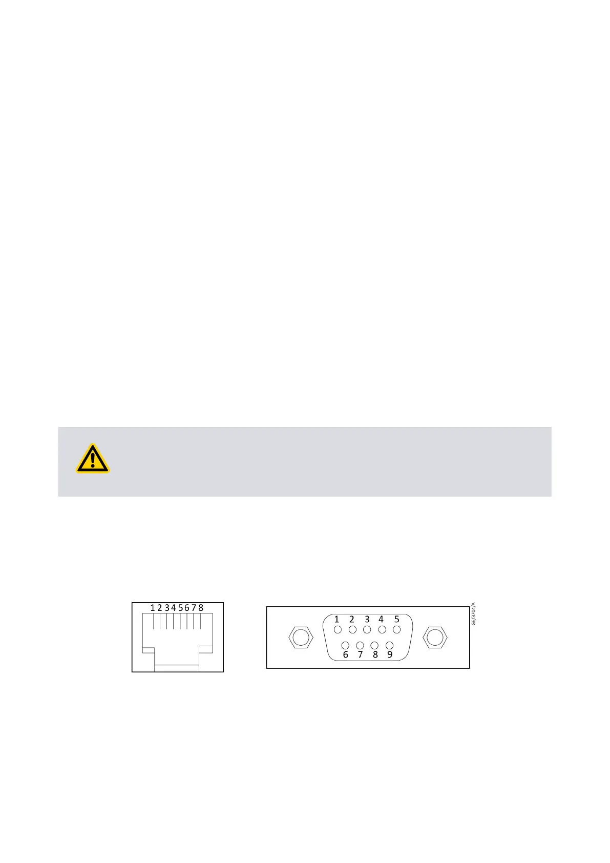
Refer to Figure: Rec
ommended electrical connecons for schemac diagram of the
electrical connecons to the gauge. Use the pins on the electrical connector as shown in
Table: Pins on the APG200 electrical connector.
Refer to Technical data on page 12 for more specicaons.
Figure 5 Electrical connectors
07/2021 - ©Edwards Limited
Page 18D1G0000880_A
D1G0000880_A - Inst
allaon