06/2016 - Art. Nr. 4200 1041 1103A 13
VSM100
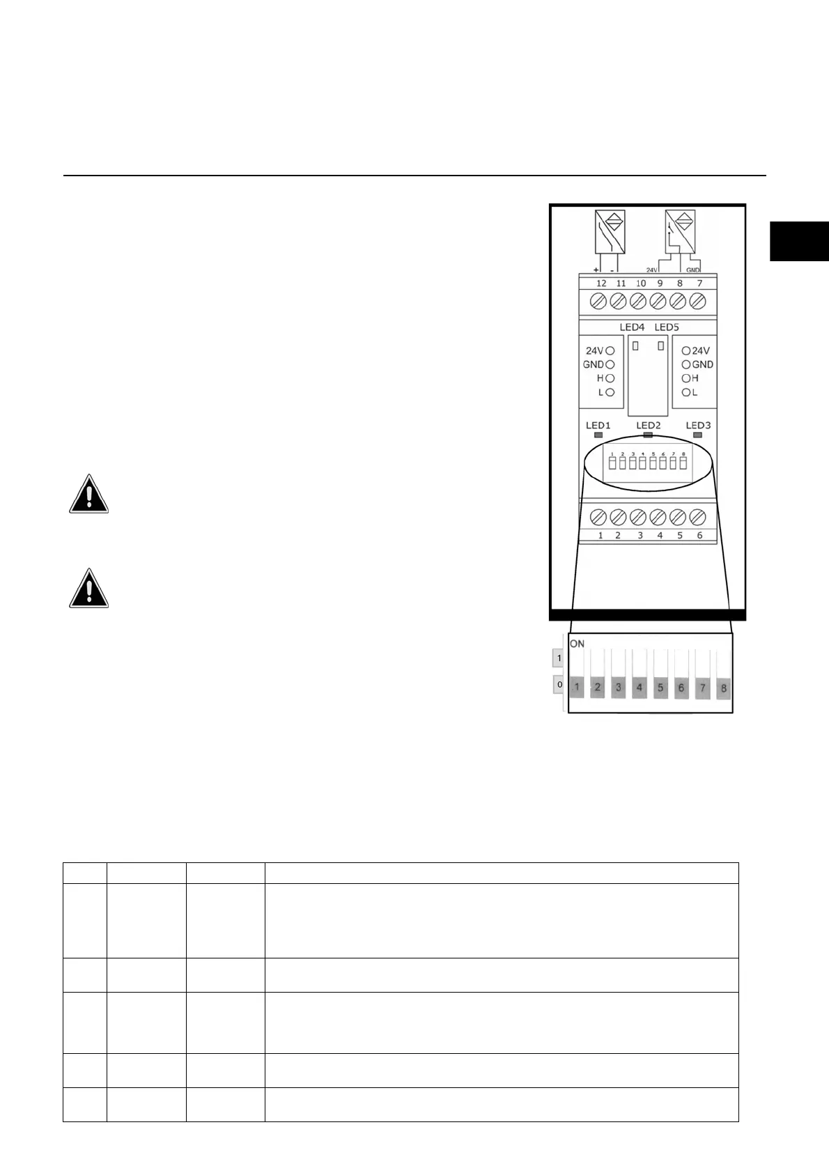
Raccordement, voir le
schéma des connexions
Commutateur
DIP
Function
VGx MV/TC burner
Speed control – VSM100 module
Module description
The VSM100 allows the BurnerTronic to control the speed of the
fan motors. The BurnerTronic treats the VSM100 as an additional
compound channel. This allows you to freely define the speed
over the entire load range. The VSM100 is connected to the
BurnerTronic via LSB. The VSM100 delivers the speed setpoint
to the motor driver (frequency converter or the like) as a 0/4–
20mA or 0–10V signal. The VSM100 records the actual speed
and sends it back to the BurnerTronic for monitoring purposes.
Either Namur sensors or 3-lead sensors with a switch output can
be used to record the speed. Feedback via a 0/4 – 20mA current
loop is also possible.
Note: it is only possible to use the VSM100 module in connection
with the LCM100 module.
Note: burners which are equipped with the VSM100 module in
the factory are preset so that the module can be used. Usually,
module settings or configuration of the BurnerTronic are not
required.
Modifications are the responsibility of the operator if a
configuration is selected which deviates in a circuit
diagram of the factory settings. The operator must
ensure that his settings are correct in that it is safe to
operate the burner. Modifications may only be carried
out by qualified trained personnel.
Incorrect setting of the DIP switches can lead to
malfunctions. Before commissioning, the setting
(DIP switch) of the LCM100 module must be checked
according to the circuit diagram. If the DFM300 is
the last device in the CAN bus chain, switch number
1 must be set to 1 (ON). The settings according to the
circuit diagram must be adhered to.
You can configure the BT3xx for the VSM100 module using the
PC software. The settings are made using parameters 403 to
406. Information on the individual parameters can be found in the
parameter list 4200 1018 1501.
LED displays
The VSM100 has 5 LEDs, enabled as follows
Pos. LED Colour Meaning
1ERR
(LED 1)
red The LED is switched off in normal operation. It illuminates under the following
conditions:
- Initialization not yet or not successfully completed (for example, because HW
could not be initialised)
- No message has been received for at least 3 seconds
2PWR
(LED 2)
green On: Module operating normally = completely initialised and without fault
3CAN
(LED 3)
green Off: CAN controller in Bus Off. Communication is not possible
Flashing: CAN controller has determined temporary faults.
The LED continues flashing for a time after the problem has been rectified.
On: CAN is ready for operation
4 Namur
(LED 4)
yellow Flashing: LED toggles whenever a pulse is received at the
Namur input. The LED flashes at half the pulse frequency
5 3-lead
(LED 5)
yellow Flashing: LED toggles whenever a pulse is received at the
Namur input. The LED flashes at half the pulse frequency
 Loading...