06/2016 - Art. Nr. 4200 1041 1103A 27
• For the next step, press
key .
The overview of the menus is
displayed, and the air and gas
flap positions settings menu is
selected.
• Open the settings menu by
pressing the key.
The access code must be
entered at this point.
(Access code 1)
• Increase or decrease the
value in increments by
repeatedly pressing or
.
• When the first figure has
been set, move the cursor to
the right by pressing .
• Repeat the operation until
you reach the last figure.
• Confirm the access code by
pressing key .
Special feature for
operation with
the frequency variator:
The fan motor is activated when menu
1 is accessed. Activation must be
confirmed, the screen is displayed as
shown on the left (Manual Handshake).
Continuous ventilation is activated for
the pre-set time period in menu 1. This
is necessary to obtain a feedback value
for the frequency variator channel. This
setting is deactivated again at the end
of menu 1.
Commissioning
Menu 1: setting the servomotors
Pre-setting without flame
Setting is carried out in 2 phases:
- Pre-setting without flame
- Setting the flame, to fine tune the
settings based on the combustion
results
When the burner is switched on, the
control and safety unit displays the
screen below.
Important
At this point, no setting position for the
servomotors has been defined,
therefore the burner cannot be started
under these conditions.
Modifying a value for the servomotor position:
- To modify the value of a position, move the cursor to the
corresponding location with the key.
- Select the value to be modified using the key, the
selected value will flash.
- Increase or decrease the value (in increments of 0.1°) by
repeatedly pressing or . For large modifications, press
and hold the or key, the value will scroll quickly up or
down.
- Confirm the new value using the key. The value stops
flashing.
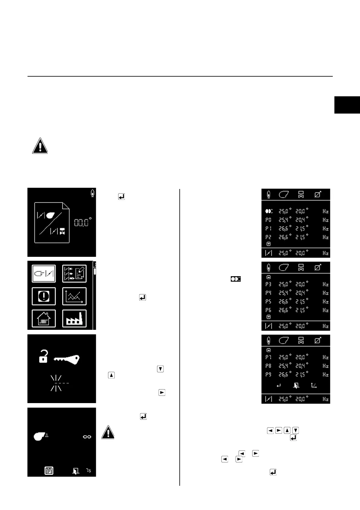
The control and safety unit
then opens the settings mode.
The screen displays the
factory pre-settings for the
different positions of the fuel
and air flap (here: for an
electronically modulated gas
burner)
The menu displays all the
settings data using three
consecutive screens (air and
gas flap positions), i.e. for:
- Ignition position: (when
the menu is opened, the
cursor is positioned here)
- Output points P0 to P9
Access codes must be entered for the individual menus at various points in these instructions. Menu areas
protected by access codes are solely reserved for authorised, qualified and trained personnel.
The following menu description explains the menu for gas operation (figures), but is also valid for fuel oil operation.
Any deviations are noted where relevant.
 Loading...